


User’s Manual
Preliminary PPC440x5 CPU Core
cache.fm.
September 12, 2002
Page 97 of 589
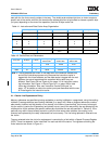
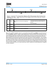
Each of the 16 SPRs illustrated in Figure 4-1 can be written from a GPR using mtspr, and can be read into a
GPR using mfspr. In general, however, these registers are initialized by software once at startup, and then
are managed automatically by hardware after that. Specifically, every time a new cache line is placed into the
cache, the appropriate victim index field (as controlled by the type of access and the particular cache set
being updated) is first referenced to determine which way within that set should be replaced. Then, that same
field is incremented such that the ways within that set are replaced in a round-robin fashion as each new line
is brought into that set. When the victim index field value reaches the index of the last way (according to the
size of the cache and the type of access being performed), the value is wrapped back to the index of the first
way for that type of access. The first and last ways for the different types of accesses are controlled by fields
in a pair of victim limit SPRs, one for each cache (see Cache Locking and Transient Mechanism on page 99
for more information).
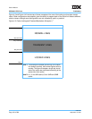
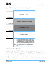
Figure 4-1. Instruction Cache Normal Victim Registers (INV0–INV3) Instruction Cache Transient Victim
Registers (ITV0–ITV3) Data Cache Normal Victim Registers (DNV0–DNV3) Data Cache Transient
Victim Registers (DTV0–DTV3)
0:7 VNDXA
Victim Index A (for cache lines with EA[25:26] =
0b00)
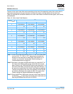
For all victim index fields, the number of bits used
to select the cache way for replacement depends
on the implemented cache size. See Table 4-3,” on
page -98
for more information.
8:15 VNDXB
Victim Index B (for cache lines with EA[25:26] =
0b01)
16:23 VNDXC
Victim Index C (for cache lines with EA[25:26] =
0b10)
24:31 VNDXD
Victim Index D (for cache lines with EA[25:26] =
0b11)
078 1516 2324 31
VNDXA
VNDXC
VNDXB
VNDXD