


Hardware Installation
2−37CM 4000 Installation and Operating Manual
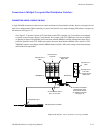
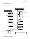
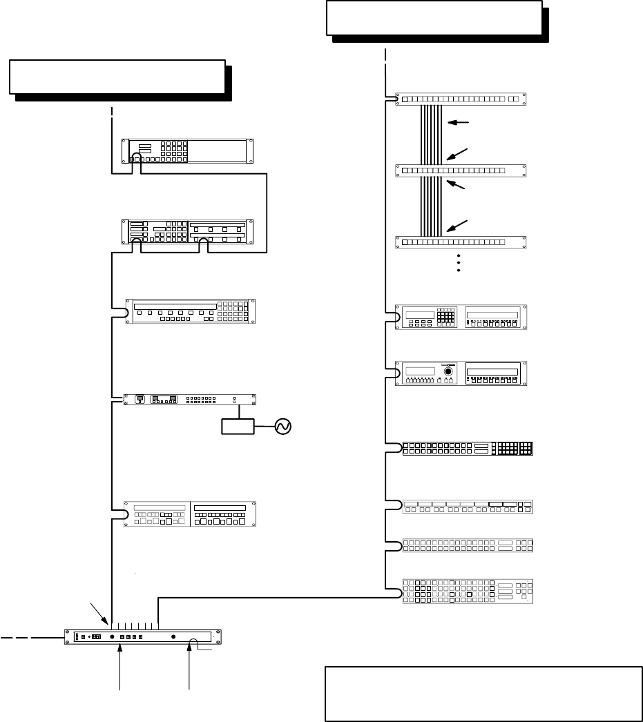
Installing Control Panels
CONNECTIONS T0 CM 4000
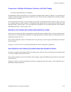
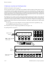
Figure 2−42. Control panel connections to CM 4000.
Serial (MPK) bus
CP 3000 Switcher Control
with expansion panel
MC 3000 Machine Control with
expansion panel
CP 3020 Push Button Control Panel
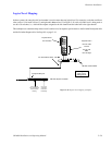
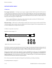
For serial data cable specifications, see page 2−63.
For Jupiter LAN cable specifications, see page 2−36.
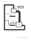
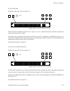
CP 3021 Push Button
Expansion Panel
12 in. ribbon cable supplied with CP 3021
“Input” connector
“Input” connector
“Output” connector
CP 3021 Push Button
Expansion Panel
4 CP 3021 max.
MC 3010/2 Dual 4−Machine
Control Panel
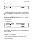
CP 300 Series Control Panel
Serial (MPK) bus
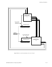
PS−20
110 V only. See page 2−38.
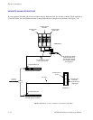
CP 3800 Control Panel
CP 3808 with CP 3809 expansion panel
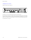
CP 3830 Control Panel
For recommended max devices see
Bus
Loading
on page 1−17
For recommended max devices see
Bus
Loading
on page 1−17.
CP 3864 Control Panel
CP 3832 Control Panel
CP 3810 Control Panel
Note: CP 3800 cannot connect to SC 3000.
CP 3824 Control Panel
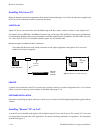
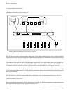
CM 4000
System
Controller
House SMPTE
time code required
for deterministic
switching
Serial
Ports
House sync
required for
vertical inter-
val switching.
10/100baseT
Jupiter LAN