


Configurator
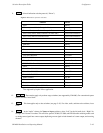
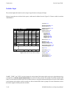
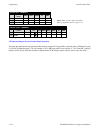
Switcher Input Table
5−50 CM 4000 Installation and Operating Manual
SPLIT SWITCHING
Split (or breakaway) switching is the selection of one input on one level and another input on another level. An example would
be the selection of color bars on the video level and test tone on the audio levels. Split switches can be manual, where the
operator addresses individual levels and makes each switch separately; or, automatic, where a single category / entry number
will cause the split to occur.
An automatic split can be arranged in either of two ways:
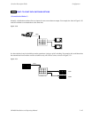
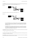
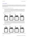
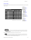
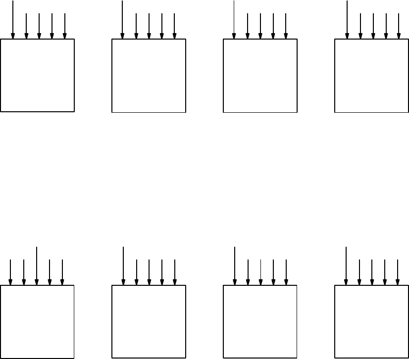
— The switcher can be wired so that the split sources arrive on parallel inputs, as shown in Figure 5−36. On the
video level, color bars are wired in as input 0. However, on the audio levels, test tone is wired in as input 0 and a
time code generator is wired in as input 0 on the time code level. The Switcher Inputs table (Figure 5−35) is
then arranged so that the input named “BARS” will switch to input 0 on all levels. This technique might be
referred to as a “hard−wired split.”
Figure 5−36. Inputs to four−level switcher, showing a “hard−wired split.”
0
Video
BARS
1234
Left audio
TONE TONE
Right audio Time code
0 1234 01234 01234
TIME CODE
GEN
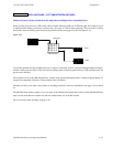
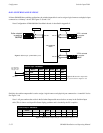
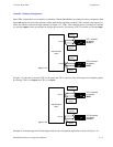
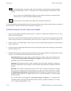
— A more flexible approach is to modify the Switcher Input table so that a single input name will address differ-
ent physical inputs from one level to another. For example, the switcher could be wired as shown in Figure
5−37, where black burst is input 64 on the video level, test tone is input 0 on the audio levels, and a time code
generator is input 0 on the time code level. The Switcher Input table is arranged so that the input named
“TONE” will switch to those inputs.
Figure 5−37. Software−controlled split.
62
Video
BLACK
63 65 66 0
Left audio
TONE
123464 0
Right audio
TONE
1234 0
Time code
1234
TIME CODE
GEN
Statusing for split switches is determined by the “I” and “P” suffixes on the Switcher Inputs table, as described in Primary
and Indirect Status Instructions on page 5−64.