


Introduction
1−20 CM 4000 Installation and Operating Manual
Example
A system is to contain the following:
S 2 channels of Saturn (1 DVP, 2 DAPs per channel). (Saturn Video and Audio Processors do
not directly contribute to Jupiter loading)
S 1 Saturn MCC 3500 Master Control Console with the Select panel used for delegation pur-
poses. (Saturn MCC 3500 panels do not directly contribute to Jupiter loading unless the Select
panel is used with a backup switcher)
S 1 Saturn DVE (Sony serial machine protocol)
S Venus router control
S 1 Triton remote router control
S 8 MC 3000 Machine Control panels
S 16 serial machines
S 1 ASCII
S 1 ESswitch (high switch rate)
S 30 CP 328 Control Panels
S 16 CP 3800 Control Panels
S 4 CP 3808 Control Panels
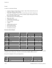
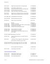
Determine the Base Multiplier
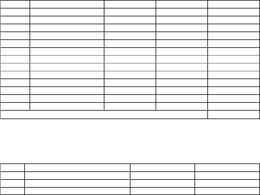
Quantity Description Base Load Factor Fixed Load Factor Total
2 Saturn DVP N/A N/A 0
4 Saturn DAP N/A N/A 0
1 Saturn MCC 3500 N/A N/A 0
1 Saturn DVE 8 8
1 Venus Router Control 20 20
1 Remote Router Control 8 8
8 MC 3000 32 (8 x 4) 32
16 Serial Machines 128 (16 x 8) 128
1 ASCII 8 8
1 ESswitch 32 32
30 CP 328 30 (30 x 1) 30
16 CP 3800 64 (16 x 4) 64
4 CP 3808 4 (4 x 1) 4
Sum of Base + Fixed Load Factors 326
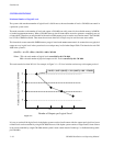
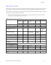
Since the sum of the base and fixed load factors of all devices in the system is greater than or equal to 320, this would be
considered a heavily loaded system. Therefore, the indicated Base Multiplier (BM) would be 2.
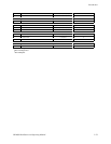
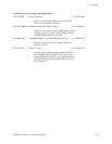
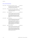
One possible configuration of this system might then be:
Board Description Loading Total
CM1 Venus Router Control 20 (FLF
1
) 20
Remote Router Control 8 (FLF) 8
30 CP 328 30 x 1 (BLF
2
) x 2 (BM
3
) 60