


CM 4000 Installation and Operating Manual S−1
Appendix S
TSL UMD Setup Guide
The TSL Under Monitor Display panels are manufactured by Television Systems Limited
(http://www.televisionsystems.ltd.uk), and can be controlled via RS−422 serial connection with VM/SI 3000 control
boards running Jupiter 7.2 or newer software.
The TSL UMD panels have RS−422 serial data and 24 V power on the same connector, so custom−built cables will be
necessary to connect the TSL UMD panels with Jupiter. Some TSL UMD panels use DB−15 connectors, and some use
RJ−45 connectors, so great care should be taken in their construction. Also, the ground pins (“0V” in the TSL manuals) on
the TSL UMD connectors should be connected to the ground pins on the Jupiter VM/SI−3000 control boards to ensure
proper communications. Please refer to the TSL UMD manual for the exact connector pinouts.
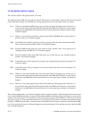
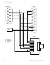
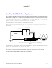
Figure S−1 is an illustration of a cable for a TSL “UMD−QD8” quad display panel (DB−15) and an “UMD−D8C” single
display panel (RJ−45), connected to a VM 3000 (DB−9).
There are some setup issues that need to be addressed. The TSL UMD−QD8 panel needs to be set in “Error Mode 3” using
the recessed front panel switches. Please refer to the TSL manual for more information on how to set that mode. All panels
need to be set in “Mode 1” to communicate with Jupiter via the serial connection.