


Hardware Installation
2−87CM 4000 Installation and Operating Manual
Connection to Automation and Other Systems
Note: The following refers to all automation−to−CM 4000 systems, including those with AccuSwitch. The
AccuSwitch application itself is described in Appendix G.
The CM 4000 will support multiple connections to an automation system (e.g., “channel A control” of an automation system
could be connected to Serial Port 1 of the CM and “channel B control” connected to Serial Port 2).
CM 4000s can be installed as a redundant pair where each monitors the other. If a fault is detected in the [active] master unit,
control will be switched to the other device automatically. For more information, see page 2−8.
Connection to Devices Using “ESswitch” Proposed ESbus Routing Switcher Dialect
“ESswitch” protocol is set on the Serial Protocol table (page 5−30); and the control computer is identified on the MPK Devices
table (page 5−107). A technical description of the proposed dialect is available; please contact Grass Valley for more informa-
tion.
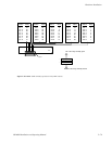
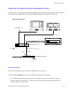
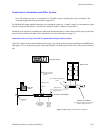
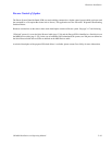
Figure 2−99. Example of Automation installation.
CM 4000 Control Module
CC 2010 Matrix (Crosspoint bus)
cables.
House SMPTE
time code required
for deterministic
switching
Binary protocol
Crosspoint bus port
ESswitch protocol
Automation system
Media converter
or Hub
Serial Port
House sync
required for
vertical
interval
switching.
CB 3000 Control Buffer
May be required when more than 50 matrix
boards are installed in switcher.
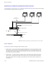
Router matrix
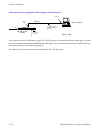
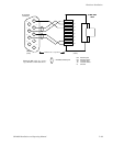
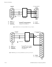
See pages 2−89 and
2−90 for examples of
this cable
Jupiter file
server
LAN