


VGA
A−9CM 4000 Installation and Operating Manual
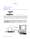
TIE LINE (PATH FINDING) PAGE
(For a general discussion of path finding, please see page 5−174.)
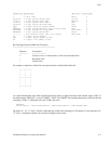
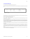
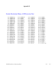
The VGA tie line display allows the user to determine which sources and destinations are using which tie lines. See Figure
A−8.
Group 1 line 0 DVE−1 > Keyer 1
line 1 VTR 2 > Monitor 1 Monitor 4
line 2 VTR 1 > G002 L03
Group 2 line 3 G002 L03 > Monitor 2
Figure A−8. Tie line display.
In path finding, there is a “Group” for each switcher level. The Group number for a given level corresponds to the actual row
number in the Pathfinding Description table (page 5−177).
The “line” number is the physical tie line in use.
The input (“DVE−1”) and output (“Keyer 1”) names are the logical names from the Switcher Input table (page 5−48) and
Switcher Output table (page 5−55).
Jupiter’s tie line management system can consist of multiple tie line usage. In other words, tie lines using other tie lines to
access a source. This state is indicated by displaying the group number and line number of the tie line instead of the input
or output number. In Figure A−8, Group 1 line 2 is carrying VTR 1; however this tie line is connected to Group 002 line 03,
which in turn is connected to Monitor 2.
If an output for a specific group/line has no tie line source connected to it, the source and destination fields will contain the
word “unused.”
The Next key will move the group/line destination field to show the next group of 1 or more destinations. A double arrow
(>>) will be displayed on a group/line row if the current row has no room to show other destinations that are switched to a
source. The message “No More” will be displayed if no more destinations for a group/line are available. The other keys are
not used.
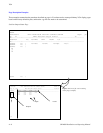
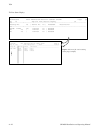
The user must define the Tie Line display page (as described below), entering the desired tie line group numbers and line
numbers. The usual limit of 25 rows per page applies.