


Configurator
Switcher Description Table
5−35CM 4000 Installation and Operating Manual
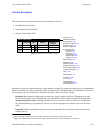
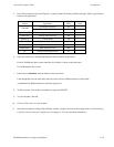
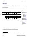
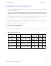
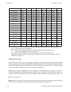
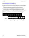
Switcher Description
Logical level
number
Logical level
name
Physical level
number
1
Switcher Description
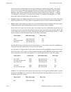
MAINROUT CM1 64 64 1 Binary None
2 MAINROUT CM1 64 64 2 Binary Left
3 MAINROUT CM1 64 64 6 Binary Right
4 MAINROUT CM1 64 64 3 Binary None
VIDEO
LEFT
RIGHT
TC
5 MAINROUT CM1 65 65 16 DM400B EnforceDATA
6
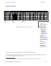
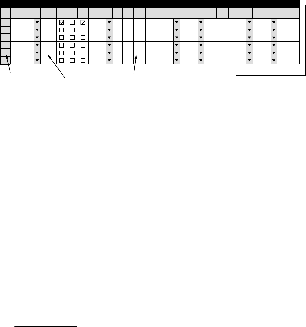
Switcher VI RV Board #In #Out PLvL Follow Level Driver 3 LI 3 LO Option AudioLevel
DM 400
MC
Off Time
Figure 5−28. Switcher Description table (example).
Password 5−22
Network Description 5−27
Serial Protocol 5−30
Switcher Description
Switcher Input 5−48
Switcher Output 5−55
Control Panel Sets
Level set 5−58
Input set 5−62
Output set 5−78
Override set 5−96
Sequence set 5−99
Category set 5−101
MPK Devices 5−107
Machines 5−135
Machine Control 5−139
Delegation Groups 5−149
Status Display Header 5−150
VGA Status Display 5−151
Tally 5−152
Path Finding 5−174
Exclusion 5−188
Y Line 5−189
Time Standard G−11
Video Reference G−14
CM VGA Options H−1
This table must be used when the CM 4000
†
is first connected to a distribution switcher.
§
Each logical level number of the switcher is given a user−specified name up to eight characters in length, and the system is
provided with detailed information about each level.
§
Some of the functions described in this section may be extra−cost options. For more information, see page 1−27.