


Hardware Installation
2−54 CM 4000 Installation and Operating Manual
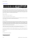
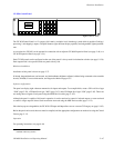
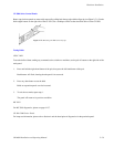
CP 3810 Panel
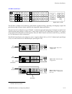
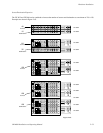
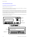
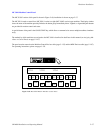
The optional CP 3810 panel can be associated with a CP 3832, CP 3864, CP 3808, or CP 3830, providing control of up to
80 outputs. The CP 3810 can also be assigned to one output, providing breakaway (split) switching and/or multi−level status.
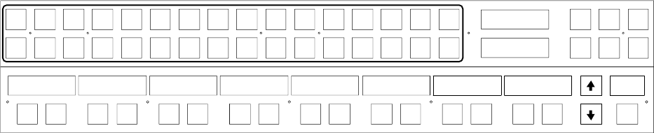
Figure 2−66 illustrates a CP 3810 with a CP 3832 panel.
VTR1 VTR2 VTR3 VTR4
VTR5 VTR6 VTR7 VTR8
CAM1 CAM2 CAM3 CAM4
CAM5 CAM6 CAM7 CAM8
BLACK
BARS TONE CG−1
SILENCE
CG−2 CG−3 CG−4
EBS1 EBS2 TEST1 TEST2 FDL1 FDL2 FDL3 FDL4
Level Menu Clear
Prot/
Lock
Pre−
set
Take
CURRENT
PRESET
VTR−001
PLAY/
STOP
PLAY/
STOP
PLAY/
STOP
PLAY/
STOP
PLAY/
STOP
PLAY/
STOP
PLAY/
STOP
PLAY/
STOP
Take/
Set
Take/
Set
Take/
Set
Take/
Set
Take/
Set
Take/
Set
Take/
Set
Take/
Set
Dest
Figure 2−66. CP 3832 (top) with CP 3810 Expansion Panel (below).
VTR−001 PG1
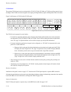
The CP 3810 can be operated in several modes:
— For multi−bus control the destination can be selected on the CP 3810 and the desired source can be selected on
the main panel (CP 3832, CP 3864, CP 3808, or CP 3830). The CP 3810 can display the names of eight destina-
tions. The “page” of eight destinations can be scrolled to display up to 80 possible destinations.
— For single−destination applications, the panel can be configured as a “CP 3810L” and operated with a main
panel or as a stand−alone unit:
S When used with a main panel, the desired destination can be selected on the main panel; the CP 3810
will display the status of eight levels. The “page” of eight levels can be scrolled to display additional
levels. A breakaway switch can be set up and executed with a single Take command.
S When used as a stand−alone status panel, the desired destination is permanently entered on the MPK
table (see Software Configuration below). The CP 3810 will display the status of eight levels. The
“page” of eight levels can be scrolled to display additional levels.
— The CP 3810 can also be used as a limited−function machine control panel, providing Play and Stop com-
mands for VTRs.
— Alternatively, it can be configured as a “CP 3810S,” meaning that the selected outputs will remain selected
until explicitly changed by the operator.
Hardware Installation
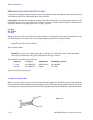
Installation of this panel is shown on page 2−37. Note that each CP 3810 panel requires a separate MPK connection.
If desired, the panel hardware can be tested, and window/button brightness adjusted, without being connected to the controller
board (CM 4000). For more information, see Diagnostics Mode on page 6−130.
Software Configuration
Each CP 3810 panel requires a separate entry on the MPK Devices table. See page 5−107.