


Hardware Installation
2−70 CM 4000 Installation and Operating Manual
EXAMPLES OF JUPITER TALLY SYSTEMS
The diagrams on the following pages show systems that can be controlled by the Jupiter Standard Tally application.
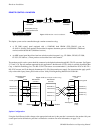
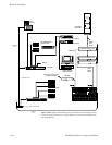
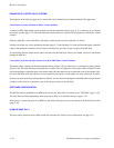
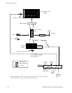
Connection to Systems with Saturn Master Control Switcher
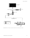
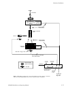
A Saturn (or MCS 2000) master control switcher can feed the transmitter directly (page 2−71) or indirectly by re−entering
the routing switcher (page 2−72). The main difference between these two systems is the tally light next to the master control
switcher.
Each tally light that is to be controlled by the Jupiter system requires one relay connection, as shown.
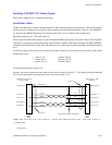
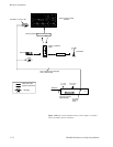
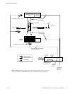
Systems can include one or more production switchers (page 2−73 and following). For each feed from the Jupiter−controlled
router to the production switcher(s), there must be a connection to one of the 40 opto−isolators of the MI 3040.
No connections from the Saturn master control switcher to the MI 3040 opto−isolators are needed; tally data is transmitted
through the MPK bus.
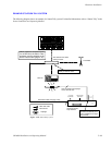
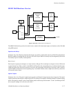
Connection to Systems with Non−Saturn, Non−MCS 2000 Master Control Switcher
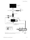
The master control switcher can feed the transmitter directly (Figure 2−87) or indirectly by re−entering the routing switcher
(Figure 2−88). The main difference between these two systems is the tally light next to the master control switcher. For each
feed from the Jupiter−controlled router to the master control switcher, there must be a connection to one of the 40 opto−isola-
tors of the MI 3040. Each tally light that is to be controlled by the Jupiter system requires one relay connection, as shown.
Systems can also include one or more production switchers. For each feed from the Jupiter−controlled router to the production
switcher(s), there must be a connection to one of the 40 opto−isolators of the MI 3040.
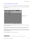
SOFTWARE CONFIGURATION
The MI 3040 must be established as an MPK device for tally use, after which it is referred to as a “MI 3040/T” (page 5−115).
The Tally Relay and Tally Dependency tables must also be filled in, as described starting on page 5−152.
When used as a connection point for an MPK bus, the Saturn video processor must be entered on the Serial Protocol table
(page 5−30).
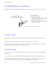
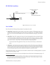
SLIMLINE UMD TALLY
The Grass Valley SlimLine series UMDs include self−powered tally LEDs. For more information, see page 2−81.