


Control Panel Operation
CP 3832 / 3864
6−109CM 4000 Installation and Operating Manual
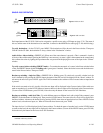
Single−Bus Operation
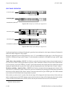
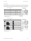
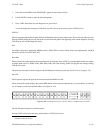
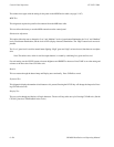
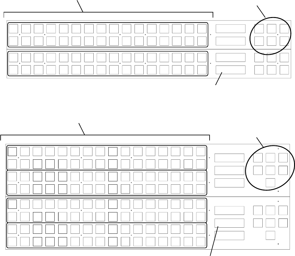
For single−bus applications, such as illustrated in Figures 6−139 and 6−140, operation is very similar to that described on page
6−101. The main difference is that only the Main panel’s control buttons (“LEVEL,” “TAKE,” etc.) are normally used. On the
expansion panel(s), the control buttons are not illuminated and the word “Source” always appears in the Preset window.
VTR1 VTR2 VTR3 VTR4
VTR5 VTR6 VTR7 VTR8
CAM1 CAM2 CAM3 CAM4
CAM5 CAM6 CAM7 CAM8
BLACK
BARS TONE CG−1
SILE
NCE
CG−2 CG−3 CG−4
EBS1 EBS2 TEST1 TEST2 FDL1 FDL2 FDL3 FDL4
Level Menu Clear
Prot/
Lock
Pre−
set
Take
CURRENT
PRESET
VTR−001
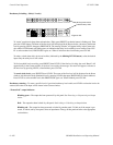
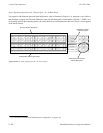
Figure 6−139. CP 3832s configured
as 64 x 1 control station.
Level
Menu Clear
Prot/
Lock
Pre−
set
Take
CURRENT
PRESET
VTR−001
SOURCE
Illuminated control buttons
indicate Main panel
All selection buttons glow green
“SOURCE” indicates
expansion panel
STU1 STU2 STU3 STU4
EDIT1 EDIT2 EDIT3 EDIT4
PST PGM AIR KEY1
KEY2
BACK
UP
BY
PASS
XMIT
VCR1 VCR2 VCR3 VCR4
VCR5 VCR6 VCR7 VCR8
AUX1 AUX2 AUX3 AUX4
AUX8AUX7AUX6AUX5
VTR1 VTR2 VTR3 VTR4
VTR5 VTR6 VTR7 VTR8
CAM1 CAM2 CAM3 CAM4 CAM5 CAM6 CAM7 CAM8
CG−1 CG−2 CG−3 CG−4
FDL1 FDL2 FDL3 FDL4
Level
Menu Clear
Chop
Lock/
Prot
Pre−
set
Take
CURRENT
PRESET
DESTINATION
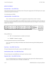
SOURCE
VTR−001
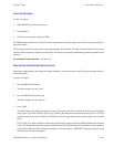
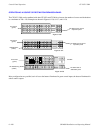
All selection buttons glow green
Illuminated control buttons
indicate Main panel
“SOURCE” indicates
expansion panel
MONITOR1
Level Menu Clear
Chop
Lock/
Prot
Pre−
set
Take
CURRENT
PRESET
DESTINATION
STU1 STU2 STU3 STU4
EDIT1 EDIT2 EDIT3 EDIT4
PST PGM AIR KEY1
KEY2
BACK
UP
BY
PASS
XMIT
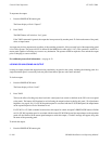
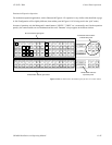
Figure 6−140. CP 3864s configured
as 128 x 1 control station.
STU5 STU6 STU7 STU8 STU9 ST10 ST11 ST12 ST13 ST14 ST15 ST16
EDIT5 EDIT6 EDIT7 EDIT8 EDIT9 ED10 ED11 ED12 ED13 ED14 ED15 ED16
BLACK
BARS TONE
SILE
NCE
EBS1 EBS2 TEST1 TEST2
AUX1 AUX2 AUX3 AUX4 AUX5 AUX6 AUX7 AUX8 AUX9 AX10 AX11 AX12 AX13 AX14 AX15 AX16
VTR9 VT10 VT11 VT12
VT13 VT14 VT15 VT16
VT17 VT18 VT19 VT20 VT21 VT22 VT23 VT24 VT25 VT26 VT27 VT28 VT29 VT30 VT31 VT32
CAM9 CM10 CM11 CM12 CM13 CM14 CM15 CM16
CG−5 CG−6 CG−7 CG−8 CG−9 CG10 CG11 CG12
VTR−001
MONITOR1