


Configurator
Path Finding
5−176 CM 4000 Installation and Operating Manual
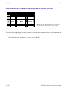
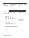
SWITCHER INPUT TABLES
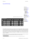
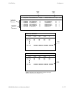
Referring to Figure 5−153 and the Switcher Input table for “NEWSROUT,” the entries for VT21 and VT22 follow the normal
pattern. However, there are also entries for VT15 and VT16—machines that are normally sources for “MAINROUT.” In the
following columns, there are Group Name selections such as “VNEWMAIN,” “LNEWMAIN,” etc. If there is a request for
VT15 to be switched to a “NEWSROUT” output, then the system is referred to Groups VMAINNEW through TMAINNEW
on the Path Finding Data table. The VMAINNEW entry, for example, shows that for video there are three tie lines available
to make this switch. Assuming that one of these lines is available, the switch will be completed.
Note: All sources identified as available through path finding must also appear on the Switcher Input table for the
“home switcher.” In the example just given, VT15 appears on both tables.
17 18 19 20 21 22 23 24 25
6
7
8
9
10
11
12
13
14
38 39 40 41 42 43 44 45 46 47 48
55
56
57
58
59
60
61
62
63
64
Distribution
switcher
“NEWSROUT”
Distribution
switcher
“MAINROUT”
65
VT16
VT15
VT22
VT21
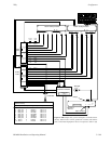
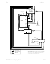
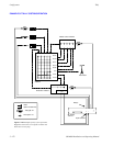
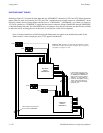
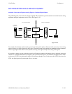
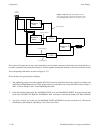
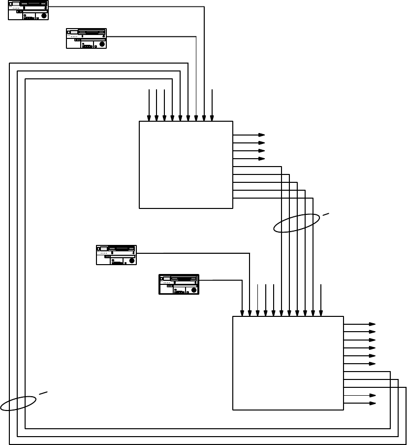
Figure 5−152. Example of sequential path finding connec-
tions between video levels of two switchers. For correspond-
ing tables, see Figure 5−153.
In this example, this group of tie
lines is named “VNEWMAIN” (vid-
eo, NEWSROUT to MAINROUT).
Other naming schemes could use
“GROUP1,” or, more elaborate
names like “V5N10M43,” meaning
“Video, 5 News lines starting at
output 10 to Main router starting
at input 43,” etc.)
In this example, this group of tie
lines is named “VMAINNEW.”