


Configurator
MPK Devices
5−107CM 4000 Installation and Operating Manual
MPK Devices
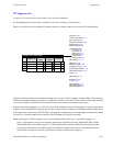
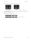
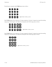
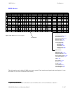
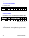
Figure 5−89. MPK Devices table (example).
STUMC MC−3000 6 00000016
STUCP CP−3000 6 00000014 KXYZ−OVE
KXYZ−SEQ
1
MPK Devices
MPK
Type
Expansion
Pass
Board
CM1
Port Address Input Sets Output Sets Level Set Overide Set Sequence Set
2
CM1 KXYZ−INP KXYZ−OUT KXYZ−LEV
Devices word
In Panel Out Panel
ENGCP CP−3000 6 00000013 KXYZ−OVE
KXYZ−SEQ
3
CM1 KXYZ−INP KXYZ−OUT KXYZ−LEV
MC CP−3000 2 00000000 KXYZ−OVE
KXYZ−SEQ
4
CM1 KXYZ−INP MC−OUT KXYZ−LEV
SHOP CP−3000 2 00000002 KXYZ−OVE
KXYZ−SEQ
5
CM1 KXYZ−INP SHOP KXYZ−LEV
DELAY CP−3000 2 00000003 KXYZ−OVE
KXYZ−SEQ
6
CM1 KXYZ−INP DELAY−OUT KXYZ−LEV
TAPECP CP−3000 6 00000008 KXYZ−OVE
KXYZ−SEQ
7
CM1 KXYZ−INP TAPE−OUT KXYZ−LEV
TAPEMC MC−3000 6 00000016
8
CM1
CONF CP−3000 3 00000006 KXYZ−OVE
KXYZ−SEQ
9
CM1 KXYZ−INP CON1 KXYZ−LEV
PROD CP−3020 6 00000012
10
CM1
3020−OVEVT01 KXYZ−LEV
TMC03010 MC−3010 6 00000029
11
CM1
EDIT CP−320 5 00000037
12
CM1 KXYZ−INP EDIT−OUT KXYZ−LEV
Hexadecimal
Device
Password 5−22
Network Description 5−27
Serial Protocol 5−30
Switcher Description 5−35
Switcher Input 5−48
Switcher Output 5−55
Control Panel Sets
Level set 5−58
Input set 5−62
Output set 5−78
Override set 5−96
Sequence set 5−99
Category set 5−101
MPK Devices
Machines 5−135
Machine Control 5−139
Delegation Groups 5−149
Status Display Header 5−150
VGA Status Display 5−151
Tally 5−152
Path Finding 5−174
Exclusion 5−188
Y Line 5−189
Time Standard G−11
Video Reference G−14
CM VGA Options H−1
This table must be used to define all MPK devices in the system. These include control panels and status displays. It is also
used when a PC is used as a Software Control Panel.
§
§
Applies only when the Software Control Panel is used for machine control. For more information, see Section 7.