


Configurator
CP Output Set
5−83CM 4000 Installation and Operating Manual
• For CP 330/6 panels, select type “CP310.” This panel does not use categories or mnemonics, but the table is
used to assign the panel’s six outputs. Press the INSERT button to start building the table. Then skip to Step
11.
• For CP 330 panels operated in dual bus mode, select type “CP3000.” This panel does not use categories or
mnemonics, but the table is used to assign the panel’s two outputs. Press the INSERT button to start building
the table. Then skip to Step 12.
• For SlimLine (and RP 1/2/3) UMD status displays select type UMD3A.
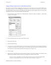
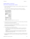
• For DD switcher applications, both E−MEM and Serial tables will probably be required. Clicking on “Ap-
ply” and “Open Table” will open a blank version of the table shown in Figure 5−67. For the E−MEM table,
skip to Step 13. For the serial table, skip to Step 14.
• For Thomson Broadcast Automation or other external computer applications, a type “Serial” table will
be required. Click on “Edit” to bring up a blank version of the CP table without a “Mnemonic” column. Press
the INSERT button to start building the table. Then skip to Step 15.
• For CP 3832/3864 panels controlling more than one output, or CP 3810L control panels, a type “CP3832”
table will be required. Click on “Edit” to bring up a blank version of the CP table. Press the INSERT button to
start building the table. Then skip to Step 16.
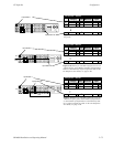
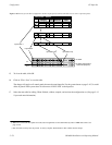
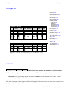
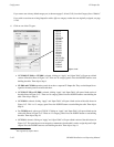
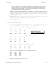
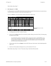
7. Clicking on an existing Output Set will open a table similar to that shown in Figure 5−67.
Figure 5−67. Output
Set table (example).
1
Output Set — MC−OUT
Category
STU
Entry
1
Mnemnonic
QC
Output
QC
Level Set Button
2
3
VTR 1 VT01 VT01
VTR 2 VT02 VT02
4 VTR 3 VT03 VT03
5
6
VTR 4 VT04 VT04
VTR 5 VT05 VT05
Auto
Mnem
Logical
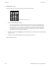
8. If you are:
— adding a new entry, click on the row number above where you want the new entry to appear. Click the “Edit”
pull−down menu. Click on “Insert” and make the addition. Then go to Steps 9 through 15 below as appropri-
ate.
Important: Row numbers on Jupiter tables are used as the “logical” numbers for destinations. Changing
the row number of a destination (by inserting/deleting a new output in the middle of the table, for example)
will disrupt control of the system, requiring controller boards to be memory−cleared and reset (see “Clear-
ing Battery−Protected Memory” in Appendix B). One way to avoid this interruption is to add new outputs
at the end of tables.
— editing an existing entry, double−click on the item you want to change. Then go to Steps 9 through 15 below as
appropriate.