


Configurator
Machines Table
5−135CM 4000 Installation and Operating Manual
Machines
1
Machines
2
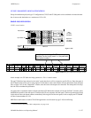
VT01 Sony Mch CM1 1
VT05 Sony Mch CM1 7
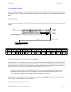
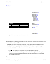
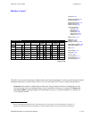
Figure 5−118. Machines table for system shown on page 5−137.
Name Type
Board Port Address
Machine Device
Password 5−22
Network Description 5−27
Serial Protocol 5−30
Switcher Description 5−35
Switcher Input 5−48
Switcher Output 5−55
Control Panel Sets
Level set 5−58
Input set 5−62
Output set 5−78
Override set 5−96
Sequence set 5−99
Category set 5−101
MPK Devices 5−107
Machines
Machine Control 5−139
Delegation Groups 5−149
Status Display Header 5−150
VGA Status Display 5−151
Tally 5−152
Path Finding 5−174
Exclusion 5−188
Y Line 5−189
Time Standard G−11
Video Reference G−14
CM VGA Options H−1
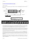
This table is the source for information about machines using Sony serial protocol. Data entered here is automatically made
available on the Machine Control table.
§
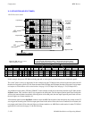
Important: Row numbers on Jupiter tables are used as the “logical” numbers for devices. Changing the row num-
ber of an existing device (by inserting/deleting a device in the middle of the table, for example) will disrupt con-
trol of the machine, requiring linkages to be reestablished. One way to avoid this interruption is to add new de-
vices at the end of tables.
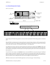
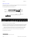
Name
This column lists the device names of all serial control machines in the system.
This is the source for machine names that appear on the control panels. Although this field will accept eight
characters, you may wish to limit machine names to four since that is the maximum that can be displayed on
the MC 3000’s expansion panel.
§
Some of the functions described in this section may be extra−cost options. For more information, see page 1−27.