


VGA
A−4 CM 4000 Installation and Operating Manual
3) Field attributes are a single digit number 0−9 immediately following the field definition.
4) The field separation character(s) is a <TAB> or <CR + LF>.
5) Switcher name is defined for every subsequent line until re−defined with another switcher name field.
6) Switcher Input and Output name are defined for the rest of the current line.
7) Level status is defined for the current column position until re−defined with another level status.
8) To assign a page−worth of data to a specific button number, use “P#4” to assign the page description data that follows
to page 4.
9) Continued Input Status uses the last defined switcher input and level from the previous line.
10) Machine Delegation is defined for the current column position until re−defined with another Machine Delegation.
11) All compiled numbers are in four−character ASCII form, NOT BINARY.
12) The Tie Line Group field will continue to the rest of the current line.
13) The number of pages for each CM 4000 VGA port is limited to 99.
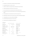
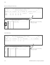
Field Definitions
Field Type Start Char Field Length Definition Syntax
−−−−−−−−−− −−−−−−−−−− −−−−−−−−−−−− −−−−−−−−−−−−−−−−−
Switcher Name S Not Displayed Sssssssss<TAB>
Output Name O 8 Onoooooooo<TAB>
Level Status (Output) l 9 lnllllllll<TAB>
Input Name I 8 Iniiiiiiii<TAB>
Level Status (Input) l Rest of line lnllllllll<TAB>
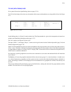
−Continued Input Status C Rest of line C<TAB>
Path Finding Status G Rest of line Gngggee<TAB>
System Time i 8 in<TAB>
System Date a 12 an<TAB>
Machine Name M 8 Mnmmmmmmmm<TAB>
Machine TMC Status m 8 mn<TAB>
Machine Delegation d 9 dndddddddd<TAB>
Machine Linkage Status k 8 kn<TAB>
Board Name B 8 Bnbbbbbbbb<TAB>
Board Message g Rest of line gn<TAB>
Board Status u 8 un<TAB>
Board Time Source s 17 sn<TAB>
Screen Text T Variable Tn−−−−−−−−−−<TAB>
Current Page Number p 2 pn<TAB>
Button Number P Not Displayed P#xx<TAB>