


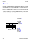
Configurator
CP Sequence Set
5−100 CM 4000 Installation and Operating Manual
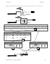
Note 2: Great care needs to be used to ensure that the switches defined in CP Sequence Sets involving Data Routers
do not conflict. Verify that each sequence uses all defined data router inputs and outputs just once, including the
implied reverse switches. Failure to do this will result in unintended switches, and possibly switching a single
input to multiple outputs at the same time.
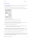
DEFINING SEQUENCES
1. On the top of the Jupiter Configurator window (page 5−2), check to see whether the configuration set you want to
change is selected for editing.
For more information, please see Modifying and Downloading a System Configuration Set on page 5−8.
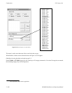
2. Click on “Jupiter > Control Panel Sets” then “CP Sequence Set.” This will open a list of all existing CP Sequence sets.
3. Click on “New.”
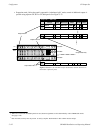
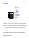
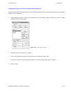
4. Enter the desired name for the set, up to eight characters, and select a CP type. Then click on “Apply” and “Open Table.”
An example of the resulting menu is shown in Figure 5−80.
Important: Do not use the same name for different CP sets. Also, do not name a CP set with a name used
by the system for a Device Type. Device Type names are shown on page 5−108.
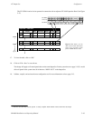
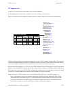
5. Add (or edit) sequences as desired.
Enter a name for the first sequence.
Select the first input name (source for these names is the Switcher Input table, page 5−48). Select the first output name.
The source for these names is the Switcher Output table (page 5−55).
Guidelines for using the editor are found on page 5−3.
The Levels column is edited by double−clicking in the field and toggling the desired levels on or off in a secondary dialog
box.
6. After saving your changes, validate, compile, and activate the configuration set.