


Introduction
1−16 CM 4000 Installation and Operating Manual
SYSTEM LIMITATIONS
Maximum Number of Logical Levels
The system−wide maximum number of logical levels is 96. However, the actual number of levels a CM 4000 can control in
a particular system varies.
The main constraint on the number of levels and outputs a CM 4000 can safely control is the available memory in PMEM,
or backed−up permanent memory. When a CM 4000 starts up, the old status tables are used to generate a completely new set
of status tables. Therefore, no more that half of the total available memory may be used to store switcher status. The CM 4000
has 512 Kb of PMEM available. That means that no more than 262,144 bytes may be used for router status tables.
This formula for router status table PMEM memory usage is based on the worst−case scenario. It assumes that every physical
output on every logical level in the system has its own unique entry in a Switcher Output Table. The formula for each CM
4000 in the system is:
(14 x TL) + (6 x TL x PO) + (10 x PO) + 600 < 262,144
Where: TL = the total number of logical levels controlled by this CM 4000
PO = the total number of physical outputs on ALL levels controlled by this CM 4000
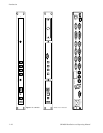
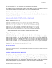
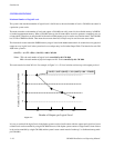
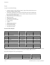
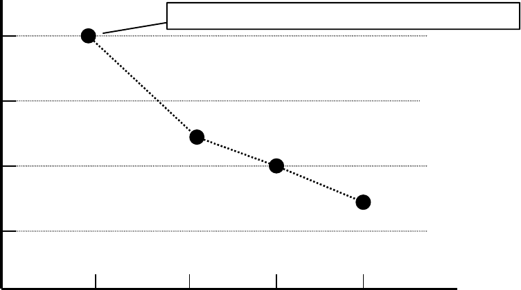
This total must be less than 262,144. For example, in Figure 2−1 a 25−level switcher can have up to 64 outputs per level.
Number of Outputs per Logical Level
Number of Levels On This CM 4000
64 128 256172
10 15 20 25
Figure 2−1.
(14x25) + (6x25 x {64x25}) + (10 x {64x25}) + 600 = 256,950
It is easy to see that if the logical levels in the Jupiter system consist of small routers with few outputs per logical level, more
of these levels can be controlled by a single CM 4000. However, if the Jupiter system consists of larger routers, fewer of these
levels can be controlled by a single CM 4000, and the system’s router control must be “broken up,” or distributed among multi-
ple CM 4000s.