


Hardware Installation
2−8 CM 4000 Installation and Operating Manual
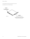
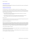
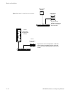
SINGLE CM INSTALLATION
If the master alarm is asserted by the main CPU watchdog timer (and assuming that the power supply is operating properly),
the CM will be rebooted automatically.
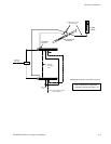
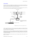
REDUNDANT CM INSTALLATION
For additional protection, a redundant (slave) CM 4000 can be installed. The slave CM 4000 monitors the master.
If a master alarm condition is detected in the master unit, control will be switched to the slave automatically. Switch over to
the redundant unit is nearly instantaneous, providing minimal disruption to the control system. The controlling CM is indi-
cated by a green light on the Activate button.
• If the controlling slave CM should later enter an alarm condition and reboot, and the master has not in the mean-
time recovered, control will remain with the slave.
• If the controlling slave CM should later enter an alarm condition and reboot, and the master has recovered by
means of an automatic reboot (e.g., after a power interruption), control will return to the master.
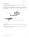
Manual Changeover
To manually change operation from the master to the slave, press the Activate button on the front panel of the slave unit. To
return operation to the master, press the Activate button on the master unit.
Replacement of a Failed Redundant Unit
Protection can be further enhanced by maintaining a third CM as a “replacement” stand−by unit. This CM can be configured
in advance with the same network address as the master. Should the master fail, and the slave assume control, the third CM
would be installed on the network and the failed master removed; the operator could then manually switch control to the new
master. This would restore the system to the original master plus slave backup arrangement and allow repair of the failed unit
with no interruption in service. To prepare a third unit as a replacement in case of failure, please refer to Appendix K.
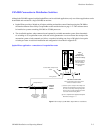
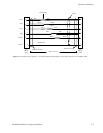
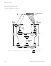
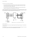
Installing Redundant CM 4000 Control Modules
In a dual CM system, the redundancy cable between the units is marked “Master” on one end; whichever CM is connected
to this end of the cable is always the master unit.
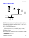
Wiring for redundant CM 4000s is shown in Figure 2−9. The BOP 4000 Break Out Panel is designed to be mounted in the
back of an equipment rack, behind the redundant CMs.