


Configurator
MPK Devices
5−127CM 4000 Installation and Operating Manual
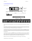
CP 3832 / 3864 MULTI−PANEL APPLICATIONS
Except for unbalanced split
§
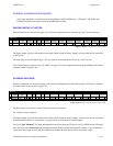
and type “L”configurations, CP 3832 and CP 3864 panels can be combined to increase the num-
ber of sources and destinations to a maximum of 128 x 128.
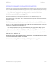
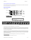
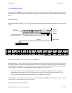
SINGLE−BUS APPLICATION
128 X 1 control station
MPK bus
Main
CP 3864
“CP3864A”
Input button 1
Expansion
CP 3864
“CP3864B”
Input button 65
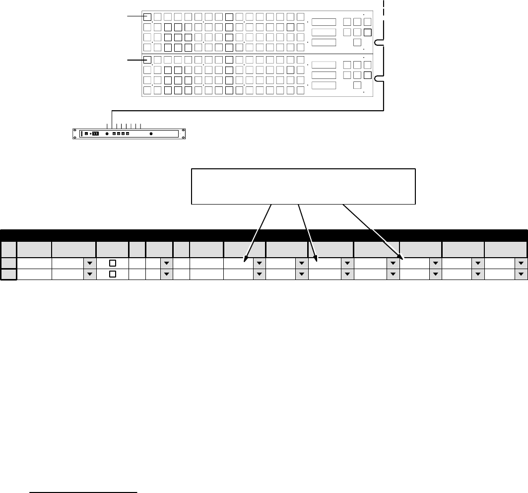
Figure 5−102.
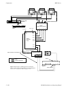
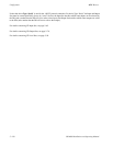
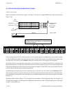
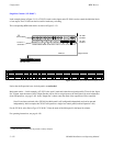
CM 4000
“CM1”
CP3864A
CP−3864
2
00000043 3832−IN MON−1
CP3864B CP−3864 2 00000044
1
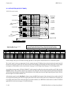
MPK Devices
MPK
Expansion
Pass
Board
CM1
Port Address Input Sets Output Sets Level Set Overide Set Sequence Set
2 CM1
KXYZ−LEV
Devices word
In Panel Out Panel
Note: Assignment of specific CP sets to a panel
identifies it as the “main” panel, i.e., the panel with
input button number 1.
Figure 5−103. Entry for system shown in Figure 5−102.
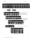
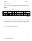
CP3864A
Device
Type
In this example, two CP 3864s are being operated as a 128 x 1 control station.
The top CP 3864 has been selected as the “main” panel; therefore it will be assigned to specific CP sets. Enter the name of
the CP Input Set that will be used to assign inputs to all the buttons at this control station (for more information about CP Input
Sets, see page 5−62). In the “Output Sets” column, enter the name of the output to be controlled. The main panel will always
have the lowest−numbered input buttons.
Any panel used to expand the number of inputs (the bottom CP 3864 in this example) will use the “In Panel” column to select
the MPK Device name of the main panel. It would use the CP sets assigned to the main panel. The first expansion panel listed
in this table will have the button numbers immediately following those of the main panel; in this example panel “CP3864B”
will have button numbers 65−128.
MPK Device table entries for other CP 3832/64 applications was discussed on page 5−109 and following.
§
For an overview of CP 3832 / 3864 configurations, see page 2−49.