


Configurator
MPK Devices
5−128 CM 4000 Installation and Operating Manual
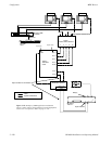
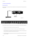
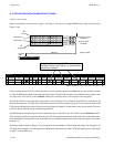
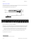
X−Y APPLICATION (WITH BALANCED SPLIT PANEL)
48 X 16 control station
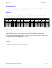
Hardware installation was discussed on page 2−49. Figure 5−105 shows an example MPK Devices table for the system in
Figure 5−104.
MPK bus
Input button 17
Expansion CP−3832
“CP3832IN”
Main CP−3832
“CP3832S”
48
sources
16
destinations
Input button 1
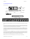
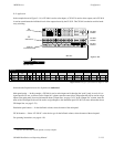
Figure 5−104.
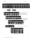
CM 4000
“CM1”
CP3832IN
CP−3832
2
00000043
CP3832S CP−3832 2 00000044 3832−IN
3832−OUT
1
MPK Devices
MPK
Expansion
Pass
Board
CM1
Port Address Input Sets Output Sets Level Set Overide Set Sequence Set
2 CM1
KXYZ−LEV
Devices word
In Panel Out Panel
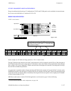
Note: Assignment of specific CP sets to a panel
identifies it as the “main” panel; i.e., the panel with
input button number 1.
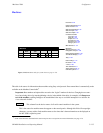
Figure 5−105. Entry for system shown in Figure 5−104.
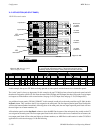
CP3832S
Device
Type
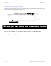
In this example, the top CP 3832 is being operated as a source expansion panel. In the MPK table, use the “In Panel” column
to select the MPK Device name of the main panel (the bottom CP 3832 in this example). Any additional source panels would
also refer to the “CP−3832S” in their In Panel column; they would use the CP sets assigned to the main panel.
The bottom CP 3832 is being operated in split mode, so the “Expansion” box is checked. The CP 3832 is considered to be
the main panel because it is being used in split mode; therefore it will be assigned to specific CP sets. Enter the name of the
CP Input and CP Output Sets that will be used to assign inputs and outputs to all the buttons at this control station. The main
panel will always have the lowest−numbered input buttons.
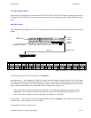
If additional panels are added to provide more destinations, they would refer to the “CP−3832S” in their Out Panel column.
They would use the CP sets assigned to the main panel. The first expansion panel listed in this table will have the button num-
bers immediately following those of the main panel; the next expansion panel listed will have the next higher set of button
numbers, etc.
The button numbers shown in Figure 5−104 correspond to the row numbers of the CP Input and Output Sets. See page 5−62
(CP Input Sets) and page 5−78 (CP Output Sets). MPK Device table entries for other CP 3832/64 applications was discussed
on page 5−109 and following.