


Configurator
Y Line
5−189CM 4000 Installation and Operating Manual
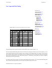
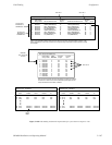
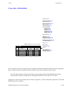
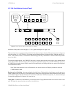
Y Line Table (DM 400/400A)
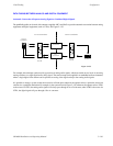
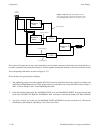
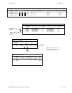
Figure 5−162. Y Line table (example).
1
Y Line Table
Level
REV (DATA)
2
FOR (DATA)
Input
VR2−S
Output
VR2−M
VR2−M VR2−S3
REV (DATA)
4
FOR (DATA)
VR1−S VR1−M
VR1−M VR1−S
Logical
Logical
Password 5−22
Network Description 5−27
Serial Protocol 5−30
Switcher Description 5−35
Switcher Input 5−48
Switcher Output 5−55
Control Panel Sets
Level set 5−58
Input set 5−62
Output set 5−78
Override set 5−96
Sequence set 5−99
Category set 5−101
MPK Devices 5−107
Machines 5−135
Machine Control 5−139
Delegation Groups 5−149
Status Display Header 5−150
VGA Status Display 5−151
Tally 5−152
Path Finding
Exclusion 5−188
Y Line
Time Standard G−11
Video Reference G−14
CM VGA Options H−1
The Y Line table is used only with Venus data routers equipped with DM 400 or DM 400A Data Matrix boards in applications
where a VTR can be used as a controller (master) on some occasions and as a tributary (slave) on others.
Note: This table is not used with newer model Venus systems equipped with the DM 400B Data Matrix boards;
these boards have software−configurable rear−panel pinout functions and do not require Y−line cables.
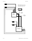
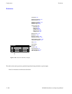
Configuration of this table is described at the conclusion of Appendix L, “Special configuration requirements: Venus DM
400/400A data matrix switching.”