


Configurator
Path Finding
5−174 CM 4000 Installation and Operating Manual
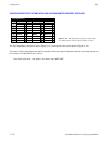
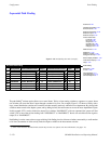
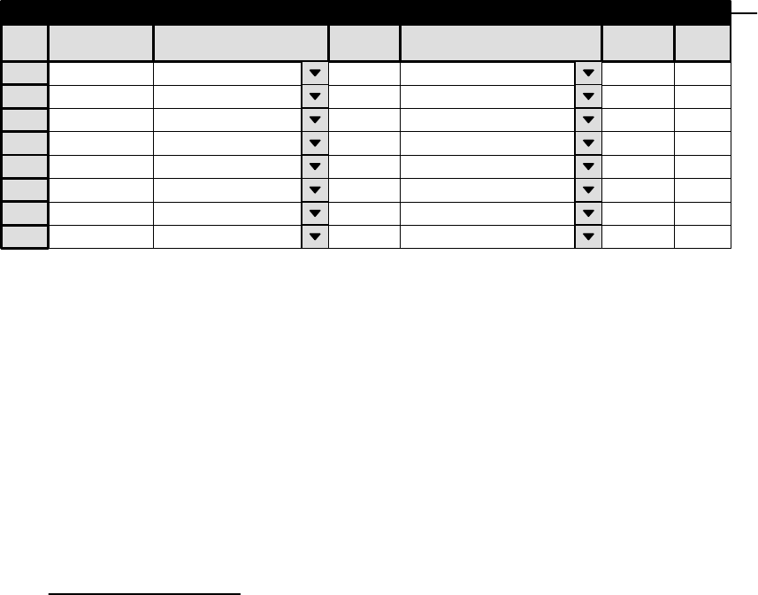
Sequential Path Finding
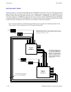
Figure 5−151. Path finding data table (example).
1
Sequential Path Finding
Source Switcher/Level
VIDEO (NEWSROUT)
Physical
10
Destination Switcher/Level
Physical
43
Count
5
2 LEFT (NEWSROUT) 10 43 5
3 RIGHT (NEWSROUT 10 43 5
4 TC (NEWSROUT) 10 43 5
5 VIDEO (MAINROUT) 61 20 3
6 LEFT (MAINROUT) 61 20 3
7 RIGHT (MAINROUT) 61 20 3
8 TC (MAINROUT) 61 20 3
Output Input
VIDEO (MAINROUT)
LEFT (MAINROUT)
RIGHT (MAINROUT)
TC (MAINROUT)
VIDEO (NEWSROUT)
LEFT (NEWSROUT)
RIGHT (NEWSROUT
TC (NEWSROUT)
Path Finding
Group Name
VNEWMAIN
LNEWMAIN
RNEWMAIN
TNEWMAIN
VMAINNEW
LMAINNEW
RMAINNEW
TMAINNEW
Password 5−22
Network Description 5−27
Serial Protocol 5−30
Switcher Description 5−35
Switcher Input 5−48
Switcher Output 5−55
Control Panel Sets
Level set 5−58
Input set 5−62
Output set 5−78
Override set 5−96
Sequence set 5−99
Category set 5−101
MPK Devices 5−107
Machines 5−135
Machine Control 5−139
Delegation Groups 5−149
Status Display Header 5−150
VGA Status Display 5−151
Tally 5−152
Path Finding
Exclusion 5−188
Y Line 5−189
Time Standard G−11
Video Reference G−14
CM VGA Options H−1
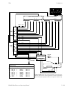
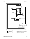
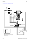
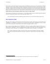
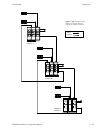
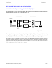
The path finding
§
software option allows two or more Venus, Trinix, or later routing switchers to operate as a system, where
one switcher can access the other’s inputs through a number of tie lines. For example, Figure 5−152 shows a facility with a
large, central distribution switcher and a smaller switcher normally used only within the news department. By placing both
switchers under control of the Jupiter system, and by adding tie lines, the main router can access the news department’s inputs.
In this example, VT21 can be switched to output 55 of switcher “MAINROUT” with one command: the system will first
switch VT21 to one of the tie lines leading from “NEWSROUT” to “MAINROUT,” then it will switch that tie line signal to
output 55 of “MAINROUT.”
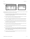
Path finding is not the same as three−stage switching. Path finding involves discrete switchers connected by a small number
of tie lines, the number of which strictly limits the inputs available at the downstream switcher.
§
Some of the functions described in this section may be extra−cost options. For more information, see page 1−27.