


Configurator
MPK Devices
5−109CM 4000 Installation and Operating Manual
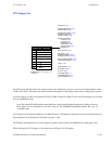
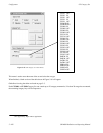
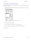
Selecting a CP 3832L or CP 3864L device type will cause the right−hand group of six buttons to function as
level selection buttons.
ES−LAN applies to the JEP−100 Jupiter / Encore Control Panel. For more information, refer to the JEP−100
manual, part no. 071 8376 xx.
Expansion
As a general rule, the Expansion box is checked when the panel is used with an expansion panel;
for example, when a CP 3000 is used with a CP 3010. For special uses of this column, see the notes below.
For each MC 3010, there is only one entry whether it is a 4 machine panel (MC 3010/1) or a dual 4 machine
panel (MC 3010/2). The right−hand panel of an MC 3010/2 is not treated as an expansion panel; therefore, the
Expansion box is not checked.
The CP 3800 panel can be defined for Multiple Destination Mode operation (front−panel selectable to Single
Destination mode); or, defined for Single Destination Mode only operation. For front−panel selectable, Mul-
tiple or Single Destination Mode operation, the Expansion box is checked. For Single Destination Mode only
operation, the box is not checked.
When CP 3808 or CP 3830 control panels are associated with a CP 3809 Expansion Panel(s), the CP
3808/3830 Expansion box is checked. The CP 3809 entry is unchecked.
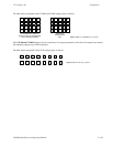
When a CP 3832 or CP 3864 control panel (including type L) is to be operated as a “split” panel, with some of
the buttons used for inputs and some for outputs, the Expansion box is checked. For all other applications, the
box is not checked (even when the panel is used in association with another panel to expand the number of
inputs or outputs, the box entry is still unchecked). The split mode cannot be combined with the continuous
Preset mode described above.
For CP 3810 Expansion Panel(s), the Expansion box is always unchecked.
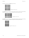
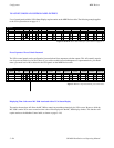
When a CP 330 is defined with the Expansion box checked and an Output Set with two or more outputs
defined, the CP 330 will operate as a 24 X 2 panel with the top row of buttons assigned to one output and the
bottom row to another. The first two outputs defined in the Output Set will be the two output buses it will
control.
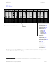
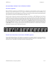
Pass
word
This table has provisions for entry of password levels (described in detail on page 5−113).
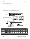
Board
Name of controller board connected to this device. The source of these names is the Network Descrip-
tion table (page 5−27).
Port
Number of controller board port connected to this device. The port must support the necessary protocol
for this device (as configured on the Serial Protocol table, page 5−30).
Address
Address (hex). Unique serial data bus ID used to select and service this device. Must be entered in
hexadecimal. (Not to be confused with LAN address entered on Network Description table shown on page
5−27).