


Configurator
Tally
5−164 CM 4000 Installation and Operating Manual
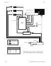
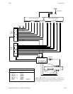
CONFIGURATION FOR SYSTEMS WITH SATURN MASTER CONTROL SWITCHER AND
PRODUCTION SWITCHER
Direct Connection to Transmitter
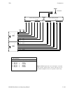
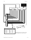
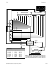
Please see Figure 5−145.
There are two types of entries on this table: MCS_TLY entries; and production switcher entries. There is no unqualified output
entry.
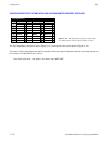
Saturn (“MCS_TLY”) entries
These entries are used in systems equipped with a Saturn Master Control Switcher (BTS MCS 2000). They allow the
Jupiter system to find out which of the sources feeding the master control switcher have been switched to the “On−air”
output. There are always five entries for the MCS 2000, one for each of the five inputs from the routing switcher. For
the Saturn, there are seven entries.
The source of the Name used here is the MPK Devices table (for discussion, see page 5−115). As a convention, the name
“MCS_TLY” is used.
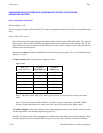
The Opto−isolator number entries must be assigned as follows:
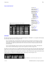
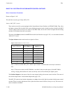
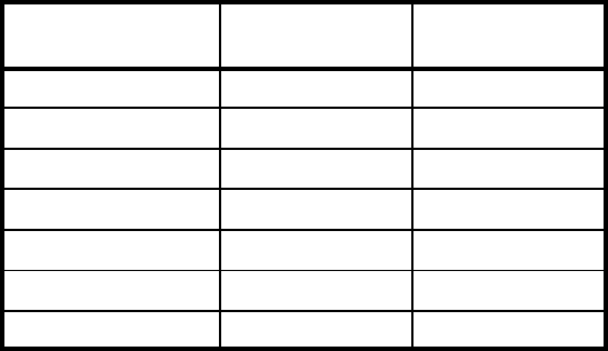
Figure 5−144.
MCS_TLY
Opto−isolator no.
Assigned to
MCS 2000 input
Assigned to
Saturn input
0 Input 1 BKGDA
1 Input 2 BKGDB
2 Key 1 KEY 1
3 Key 2 KEY 2
4 −−− MIX 1
5 −−− MIX 2
6 Bypass BYPASS
Note 1: The device called “MCS_TLY” and the “opto−isolators” associated with it exist only in software
tables.
Note 2: There are no entries for MCS 2000 Mix 1 and Mix 2 (these are audio inputs). If the MCS 2000 is
mixing or keying, then both the mix source and the key source will be tallied by the Jupiter system.
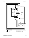
The Switcher Outputs are the names of the five router outputs leading the master control switcher. The source of the
switcher output names is the Switcher Output table (page 5−55).
The MCS_TLY entries do not include a dependency on a relay, since no tally light is associated with the MCS. (There
is no tally light because in this system the MCS is always on−air.) The last two columns are therefore left blank.