


CM 4000 / AccuSwitch
G−7CM 4000 Installation and Operating Manual
ACCUSWITCH SOFTWARE INSTALLATION
Software Installation is described in the Field Engineering Bulletin supplied with the software package.
ACCUSWITCH SOFTWARE CONFIGURATION
For AccuSwitch applications, the CM 4000 must be configured using the Network Description, Serial Devices, Switcher De-
scription, and MPK tables as described below. There are also two new tables that apply specifically to the CM: Time Standard
and Video Reference.
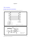
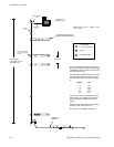
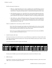
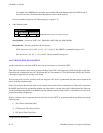
1. Network Description table. This table must be used when the CM is first installed on the LAN. Each board is given a
user−specified name up to eight characters in length. For AccuSwitch applications, the board is identified as type “AS.”
The Ethernet address in hexadecimal is entered as shown on the front of the module.
0080CE010100
Redundant
2
Network Description
Board Name
CM1
0080CE010101AS
Address
3
1
Type
Address
Figure G−6. Example Network Description table.
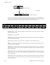
In a redundant CM system, the redundancy cable between the units is marked “Master” on one end; whichever CM is
connected to this end of the cable is always the master unit. The hardware address of the master is entered in the “Ad-
dress” column. The hardware address of the redundant (“slave”) unit is entered in the “Redundant Address” column.
For more information about redundant installations, see page 2−8.
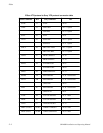
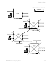
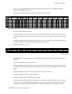
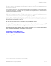
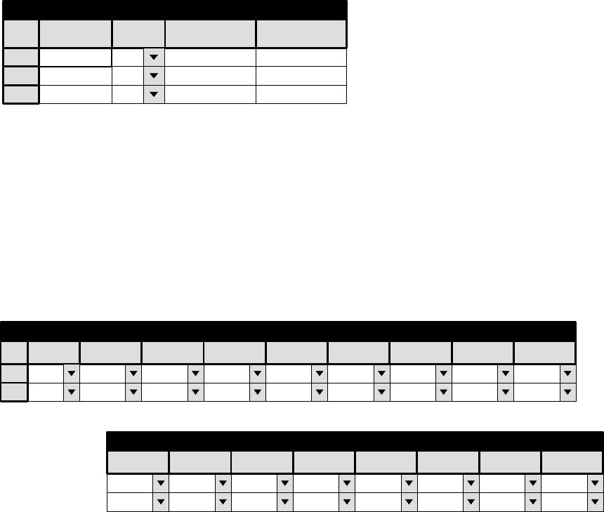
2. Serial Devices table. This table is used when the automation system is connected to one of the CM serial ports. Enter
the name of the board, as previously entered on the Network table. Then select the protocol for the port(s) to be used.
2
Serial Protocol
1
CM1 ASC
Board
(CM 1)
Protocol 1/2 -
ASC
(CM 2)
Protocol 3/4 -
ASC
(CM 3)
Protocol 5/6 -
ESW
(CM 4)
Protocol 7/8 -
ESW
(CM 5)
Protocol 9/10 -
ESW
11/12 - (CM 6)
Protocol
CET
13/14 - (CM 7)
Protocol
CET
15/16 - (CM 8)
Protocol
9600
(CM 1)
Baud 1/2 -
(CM 2)
Baud 3/4 -
(CM 3)
Baud 5/6 -
(CM 4)
Baud 7/8 -
(CM 5)
Baud 9/10 -
(CM 6
Baud 11/12 -
(CM 7)
Baud 13/14 -
(CM 8)
Baud 15/16 -
38400 115K 9600 19200 115K 4800 115K
Figure G−7. Example Serial Protocol
table.