


Configurator
CP Level Set
5−58 CM 4000 Installation and Operating Manual
CP Level Set
1
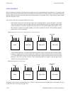
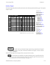
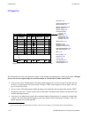
CP Level Set — KXYZ−LVL
Mnemonic Level Break Switch
2
3
VID VIDEO (MAINROUT)
LEFT LEFT (MAINROUT)
RGHT RIGHT (MAINROUT)
4 TC TC (MAINROUT)
Figure 5−45.
Figure 5−46.
Password 5−22
Network Description 5−27
Serial Protocol 5−30
Switcher Description 5−35
Switcher Input 5−48
Switcher Output 5−55
Control Panel Sets
Level set
Input set 5−62
Output set 5−78
Override set 5−96
Sequence set 5−99
Category set 5−101
MPK Devices 5−107
Machines 5−135
Machine Control 5−139
Delegation Groups 5−149
Status Display Header 5−150
VGA Status Display 5−151
Tally 5−152
Path Finding 5−174
Exclusion 5−188
Y Line 5−189
Time Standard G−11
Video Reference G−14
CM VGA Options H−1
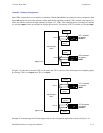
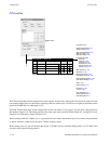
The CP Level Set table is used to assign levels to control panels. In most cases, control panels are allowed to control all levels,
but creating multiple CP Level Sets allows restricting control to certain levels. Level Sets are assigned to individual control
panels on the MPK Devices table (page 5−107).
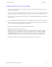
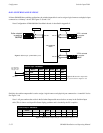
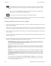
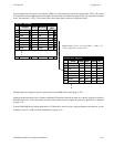
Selecting “Control Panel Sets” on the configuration set table list (Figure 5−22 on page 5−25) will open a dialog similar to
that shown in Figure 5−45. This dialog can be used to create, open, copy, and delete Control Panel sets. A example of a com-
pleted CP Level Set table is shown in Figure 5−46.
When creating a name for a Jupiter set, it’s a good practice to use letters and numbers only. If you want to use punctuation
or special characters, check the list on page 5−7 before creating a name.
When creating a new set, you will asked for the set type: “CP 3000” (for four−character display panels), or “CP−3800” series
(for most eight−character display panels).