


Hardware Installation
2−11CM 4000 Installation and Operating Manual
Connection to Serial−Control Routers
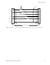
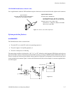
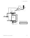
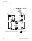
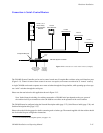
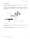
Figure 2−11. Connection to serial control routers (example).
Level 0
Serial Switcher
Crosspoint Bus port
Level 3
Serial Switcher
Level 4
Serial Switcher
Level 5
Serial Switcher
Levels 1, 2, 6
Grass Valley
Crosspoint Bus
Switcher
CM 4000 System Controller
House SMPTE
time code required
for deterministic
switching
Serial
Ports
House sync
required for
vertical inter-
val switching.
LAN
The CM 4000 System Controller can be used to control certain non−Crosspoint Bus switchers using serial interface ports
(Figure 2−11). Control of some of these routers is an extra−cost option; such routers are referred to as “remote” routers.§
A single CM 4000 can be used to operate one or more switchers through the Crosspoint Bus, while operating up to four sepa-
rate “serial” switchers through the serial ports.
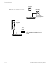
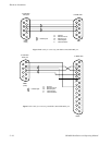
Please note the restrictions for this application shown in Figure 2−12.
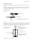
Note: Vertical interval switching of a switcher connected to a CM 4000 serial port depends on the sync system of
the switcher itself. Sync connections to the CM 4000 have no effect on the operation of the serial switcher.
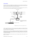
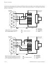
The CM 4000 must be configured using the Network Description table (page 5−27); Serial Protocol table (page 5−30), and
Switcher Description table (page 5−35).
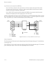
Please refer to the following pages for details concerning each switcher type. The manual supplied with the switcher should
also be checked for port configuration instructions.
§
For more information about Jupiter options, see page 1−27.