


Configurator
Tally
5−159CM 4000 Installation and Operating Manual
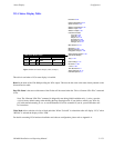
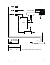
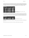
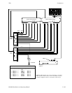
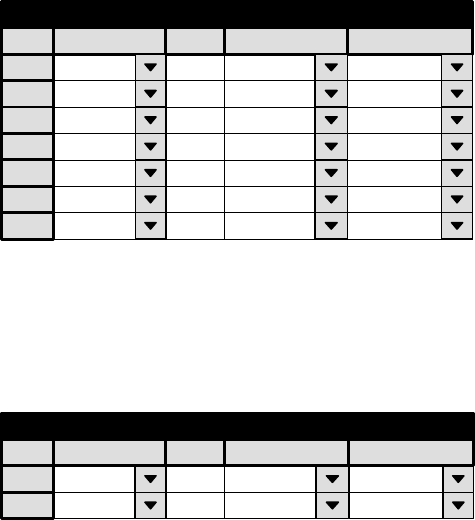
If the main output is fed from a switcher other than the router (such as a master control switcher), then the main output is not
identified as such. Instead, the names of all possible routing switcher outputs that could be selected for the main output are
listed (“Output” column in Figure 5−139). In this case, the master control switcher must tell the Jupiter system which routing
switcher output has been selected; this is done by energizing the appropriate opto−isolator (“Name/Opto” columns).
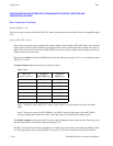
Figure 5−139. Entry used when main output is fed by
switcher other than router.
1
Tally Dependency
Tally Device
MCS_TLY
Opto
0
Logical Output
MAIN−A
Tally
2 MCS_TLY 1 MAIN−B
3 MCS_TLY 2 KEYINS1
4 MCS_TLY 3 KEYINS2
5 MCS_TLY 4 MIXINS1
6 MCS_TLY 5 MIXINS2
7 MCS_TLY 6 BYPASS
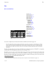
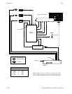
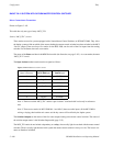
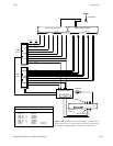
There may be additional switching layers other than the router (such as a production switcher). In this case, the system must
be able to determine (a) whether the switcher is on the air, and if it is, (b) which routing switcher output has been selected.
An entry to the “Tally” column (Figure 5−140) will identify the tally light associated with the switcher; if the light is on, then
the switcher is on the air. If it is on the air, the opto−isolators will be checked to find out which router output has been selected.
Figure 5−140. Additional switcher entries.
1
Tally Dependency
Tally Device
TALLY1
Opto
0
Logical Output
PROD1
Tally
TALLY1 /3
2 TALLY1 1 PROD2 TALLY1 /3
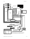
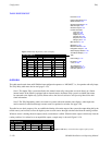
The source of the Tally column data (name of MI 3040 / relay number connected to each tally light) is the Tally Relay table
(page 5−152).
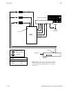
Entries for specific systems are shown below; this is followed by a detailed example of system operation.