


Control Panel Operation
CP 3800
6−28 CM 4000 Installation and Operating Manual
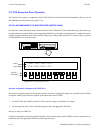
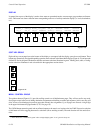
DISPLAY
In general, the top row of the display is used to show status or operational modes, error messages, page numbers and instruc-
tions. The bottom row shows selection items corresponding to the row of soft keys under the display (i.e. levels, destinations,
etc.).
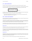
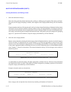
VTR_01 VTR_02 VTR_03 ENGNRING STUDIO_A STUDIO_D MONITR45 MONITR46
Camera_1 Camera_2 Studio_a Clr_Bars VTR_02 NetworkA NetworkABlack
F1 F2 F3 F4 F5 F6 F7 F8
Figure 6−30.
1
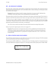
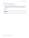
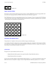
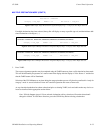
SOFT KEY GROUP
Eight soft keys are arranged across the bottom of the display to correspond with the display space above each button. These
buttons are dynamically reassigned depending upon the mode selected in the Menu Mode Group (Figure 6−32) and upon the
defined CP sets for the panel. Destination selections and menu selections illuminate in green.
†
Pending level, audio, or config-
uration selections illuminate in red as described in the appropriate sections below.
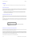
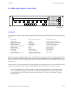
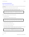
UNDO
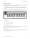
TAKE
Figure 6−31.
MENU / CONTROL GROUP
The up/down buttons (Figure 6−31) provide scrolling control over all defined menu pages. They will not scroll to any unde-
fined pages except in the case of adding destination assignments and defining overrides and sequences; in this case, they will
allow access to one blank page beyond any page that currently has assignments. Up to 20 pages are allowed. A single digit
in the upper left denotes the page number (1−9, 0 for page 10).
The UNDO button returns the panel and any affected outputs to the state it was in prior to the last TAKE. Successive selection
of this button will allow toggling between two selections (allows undoing an undo). The undo function will also undo Over-
rides.
†
In this discussion, “illuminate in green” refers to high (bright) green. “Low” green is always on.