


Hardware Installation
2−6 CM 4000 Installation and Operating Manual
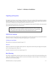
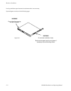
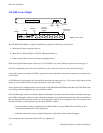
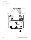
CB 3000 Control Buffer
Figure 2−6. CB 3000.
SELECT
A
SELECT
B
CLEAR
A
POWER
B
POWER
REM/ALM
OUTPUT
(CONTROL)
BUSES
CROSSPOINT
BUS LOOP
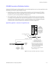
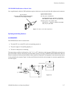
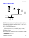
The CB 3000 Control Buffer is required for buffering crosspoint data when the system includes:
• More than 96 Venus crosspoint boards, or
• More than 50 TVS/TAS 3000 or TVS/TAS 2000 matrix boards, or
• If the Crosspoint Bus is sent to more than one equipment rack.
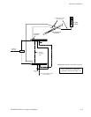
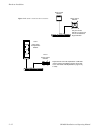
Each of the eight CB 3000 outputs can drive up to 50 (TVS/TAS) or up to 96 (Venus) crosspoint boards. See page 2−3.
For Trinix requirements, please refer to the “Planning” section of the Trinix Planning and Installation Manual.
Apex audio routers do not require a CB 3000—regardless of system expansion—because the crosspoint bus is connected only
to one chassis.
A CB 3000 may also be needed if the system includes more than one router type (e.g., a Trinix and an Apex) and one of the
routers is at or near the bus limit. For more information, contact Grass Valley.
Some systems may be equipped with one or more single−output CB 2000 Control Buffers rather than a CB 3000. Please refer
to the wiring information supplied with your switcher for details.
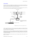
Each CB 3000 output contains two identical channels, with channel A normally used; this condition is indicated by the eight
green LEDs in the display window. If a fault is detected in channel A, that output will automatically switch to channel B; in
this case the green LEDs would be off and one or more red LEDs would be on. If a changeover occurs, first check to see if
the unit will return to normal operation by pressing the SELECT A button:
— If the unit returns to channel A operation, but a red LED remains on, press CLEAR. If the red LED(s) go off, it
can be assumed that the unit is fully operational.
— If the unit immediately returns to channel B operation, contact Grass Valley Technical Support.
For a description of the front panel window LEDs, see Appendix R.