


Configurator
Tally
5−153CM 4000 Installation and Operating Manual
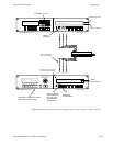
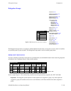
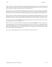
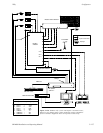
Figure 5−133 shows a tally system with a Jupiter−controlled routing switcher, a Saturn (or non−Saturn) master control
switcher, and a direct feed to the transmitter. The corresponding Tally Relay Descriptions table is also shown. Notice that the
table remains the same whether or not a Saturn master control switcher is used.
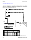
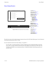
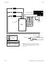
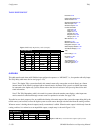
Figure 5−134 shows a system with a Jupiter−controlled routing switcher, Saturn (or non−Saturn) master control, and a produc-
tion switcher. The master control switcher is connected directly to the transmitter. The corresponding Tally Relay Descrip-
tions table is also shown. Notice that the table remains the same whether or not a Saturn master control switcher is used.
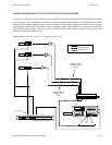
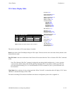
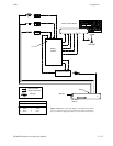
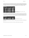
Figure 5−135 shows a system in which the master control switcher is connected to the transmitter indirectly, i.e., by re−entry
through the routing switcher. Again, the figure includes the corresponding Tally Relay Descriptions table. In this case, a tally
light for the master control switcher must be identified in the table (but not necessarily installed, as described previously).
The table is also used for systems with SlimLine (and RP 1/2/3) Status Displays, when an MI 3040 is being used to trace inputs
back through a production switcher. See page 5−121.
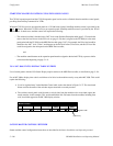
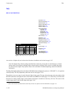
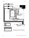
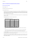
Figure 5−136 shows a system with SlimLine Status Displays when the front panel tally lights are used. The Tally Relay De-
scription table must include a one−row entry for each tally light pair. The source for the “Name” is the MPK Devices table
(page 5−94); the “Relay” entry is always “1” and the “Switcher Input” number is an existing switcher input name as defined
on the Switcher Input table (page 5−48). The “Switcher Input” entry is not actually used, but to satisfy the compiler a name
must be entered which is unique within this table.
In all cases, the Tally Dependency table must also be completed, as described on page 5−158.