


Configurator
Path Finding
5−182 CM 4000 Installation and Operating Manual
01
16
17
“MAINROUT
LEFT”
A TO D
CONVERTER
D TO A
CONVERTER
1819
26
27
“MAINROUT
AES”
“VTR1”
(ANALOG)
6
7
“MAINROUT
RIGHT”
45
“VTR2”
(DIGITAL)
TIE LINE GROUP 1
TIE LINE GROUP 3
TIE LINE GROUP 4
TIE LINE GROUP 2
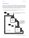
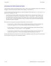
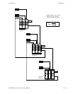
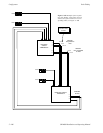
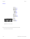
Figure 5−156. Example of automatic conver-
sion system (video connections not shown). For
corresponding table entries, see Figure 5−157.
This system will require four tie lines, with a dedicated A to D converter connected to the first pair and a dedicated D to A
converter connected to the second pair. Each pair is “locked” together, meaning that selection of one result in selection of both.
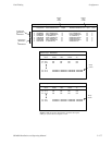
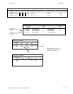
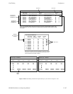
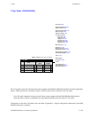
The corresponding table entries are shown in Figure 5−157.
There are three rules governing this technique:
1. The pathfinding groups to be locked together MUST have identical digital Switcher Names, digital Level Names, and
digital Physical Input/Output entries. These groups must be on consecutive rows of the table. Please refer to Groups 1
and 2, as well as Groups 3 and 4, in the Pathfinding Data table.
2. In the Switcher Description table, the “MAINROUT LEFT” level and “MAINROUT RIGHT” level must be controlled
by the same VM 3000 / CM 4000. The “MAINROUT AES” level may be controlled by another VM 3000 / CM 4000.
3. Any levels “sourced” by, in this case, the MAINROUT LEFT and RIGHT levels may not break away. This must be
established by unchecking the “Breakaway” box in the CP Level Set.