


CM 4000 / AccuSwitch
G−8 CM 4000 Installation and Operating Manual
The CM serial protocol selections are:
S ESW (a.k.a. “Jupiter ESswitch protocol”). This is a simplified version of the ES Tributary protocol. It
is described in Grass Valley document “ESswitch Serial Routing Switcher Control Protocol, En-
hanced Version.” (The protocol description used as a reference should be dated June 2001 or later.)
S CET (ES Tributary) protocol, a.k.a. “CM_ESTR.” This is the full tributary ESBus automation proto-
col, compliant with SMPTE EG 29−1993, and all associated normative references. The protocol sup-
ports all standard bit rates from 300 to 115.2 kBPS. Flow control is an advantage with this protocol.
S ASC (ASCII) (a.k.a. “Jupiter ASCII Interface Protocol”). This protocol is described in Appendix N
(the protocol description used as a reference should be dated June 2001 or later). If this protocol is
used, the developer should read “A note concerning level numbering and external control computers
using ASCII protocol” on page 5−60.
If there is a redundant CM, it is not necessary to define it on this table.
Note 1: Grass Valley recommends that all eight ports be defined regardless of how many are actually
used. Even if there is no serial connection at all (e.g., in the case of an automation system connected via
LAN) all eight should still be defined in this version of the software.
Note 2: For every port defined in the Serial Protocol table there must also be an entry in the MPK De-
vices table, otherwise the CM 4000 will not boot.
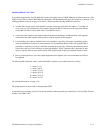
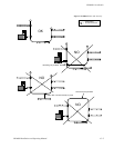
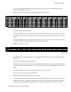
3. Switcher Description table entries.
Each logical level number of the switcher is given a user−specified name up to eight characters in length, and the system
is provided with detailed information about each level. The name of the CM 4000 connected to the switcher is entered
in the “M Board” column.
At least one switcher level must be assigned to the CM 4000.
1
Switcher Description
MAINROUT CM1 64 64 1 Binary None
2 MAINROUT CM1 64 64 2 Binary Left
3 MAINROUT CM1 64 64 6 Binary Right
VIDEO
LEFT
RIGHT
Switcher VI RV Board #In #Out PLvL Follow Level Driver 3 LI 3 LO Option AudioLevel
DM 400
MC
Off Time
Figure G−8. Example Switcher Description table.
The name of the CM 4000 (as per the Network Description table) is entered in the “M Board” column.
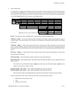
4. MPK table entries.
Control devices connected to the CM 4000 are entered on this table. (Although an automation system is not an actual
“MPK” device, it must still be entered on this table.)