


Hardware Installation
2−24 CM 4000 Installation and Operating Manual
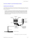
DATATEK D−2000/2166 CONNECTIONS
The CM 4000 can be connected to a Datatek D−2166 Buffer Control Module, which in turn is connected to a D−2000 Series
routing switcher (see page 2−24). The protocol setting is: 38400 baud, 8 data bits, even parity, 1 stop bit.
Although the CM 4000 is connected to one of the D−2166 Buffer Control Module ports labelled “RS−232,” the port must
be set with an internal jumper to operate according to RS−422. Refer to the manual supplied with the D−2166 for more infor-
mation.
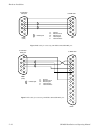
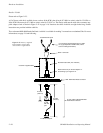
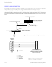
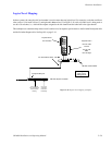
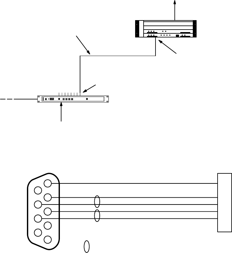
Figure 2−28. Connection to Datatek D−2166 Buffer Control Module.
See Figure 2−29 for a description of this cable
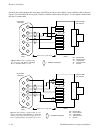
Datatek protocol
“RS−232−C A” or
“RS−232−C B” port
jumpered for RS−422 operation
to D−2000 series routing switcher
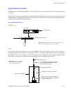
D−2167 Buffer Interface and
D−2166 Buffer Control Module
in DF−2115 Rack Frame
House time
code
(optional).
See pg.
2−64
CM 4000 System Controller
Serial Port
LAN
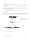
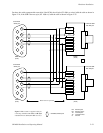
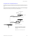
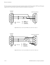
Figure 2−29. Cable for connecting CM 4000
to Datatek D−2166 Buffer Control Module.
1
6
R−
2
7
3
T−
8
4
9
5
T−
R+
to CM 3000
serial port
to Datatek D−2166/DF−2115
“RS−232−C A” or “RS−232−C B” port
jumpered for RS−422 operation. Refer
to the manual supplied with the Datatek
router for more information.
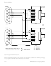
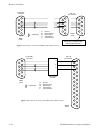
G Ground
R− Receive minus
R+ Receive plus
T+ Transmit plus
T− Transmit minus
DB9P
(male)
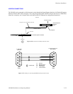
= twisted pair
T+
R−
R+
G G
T+