


Hardware Installation
2−41CM 4000 Installation and Operating Manual
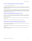
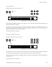
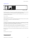
CP 330 Control Panel
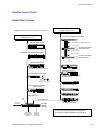
Installation of this panel is shown on page 2−37.
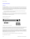
Figure 2−46. CP−330 Control Panel (as supplied).
CHG
VID
CHG
A1
CHG
A2
CHG
A3
CHG
A4
CHG
A5
012
(etc.)
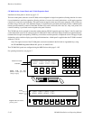
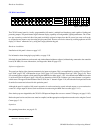
The CP 330 can be configured to operate as a 48 x 1 panel, or, as a 24 x 2 panel with the top row of buttons assigned to one
output and the bottom row to another.
Installation is very similar to the CP 300 (page 2−38). However, for the 24 x 2 application, on the MPK Devices table, a “Y”
is entered in the Expansion Panel column, and, the entry in the Output Set column is the name of an actual Output Set. This
Output Set must show the names of the two destinations.
For operating instructions, see page 6−1.
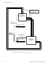
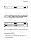
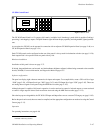
CP 330/6 48 x 6 Six Bus Control Panel
Installation of this panel is shown on page 2−37.
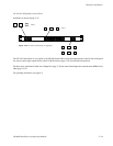
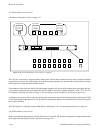
Figure 2−47. CP−330/6 Control Panel (as supplied).
012
345
012
(etc.)
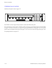
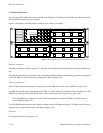
The CP 330/6 Control Panel is very similar to the CP 300 Control Panel, except that six buttons on the right side of the panel
are used to control six outputs. Refer to the CP 300 discussion (page 2−38) for installation instructions.
The buses to be controlled are listed in an “Output Set” (page 5−78); the name of the Output Set is entered on the MPK Devices
table (page 5−107).
For operating instructions, see page 6−5.