


GV 8964OMD OSD Module
CM 4000 Installation and Operating ManualT−2
JUPITER CONFIGURATION PROCEDURE
1. Network Description table: Each module frame requires a separate row on this table. The board Type is “MN”
(Modular Network board). In the Address field enter the IP address of the frame’s network card.
2. MPK Devices table and CP sets.
The MPK Devices table requires an entry for the module frame, and a separate entry for each video channel of each
OSD board.
Module frame entry
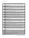
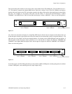
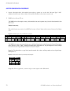
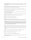
The module frame entry consists of an MPK Device name, a Device Type, and the names of three sets. See Figure
T−2.
Figure T−2. Module frame entry on MPK table (example).
MNF1 MNF MNF−IN MNF−OUT
1
MPK Devices
MPK
Expansion
Pass
Board Port Address Input Sets Output Sets Level Set Overide Set Sequence Set
2
Devices word
In Panel Out Panel
MNF−LEV
Device
Type
The MPK Device name must be exactly the same as the Board Name for the module frame on the Network Description
table. The Device Type is “MNF” (Modular Network Frame). Of the three sets, only the Output set is used; the Input
Set and Level Sets are placeholders needed to satisfy the compiler.
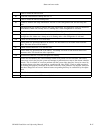
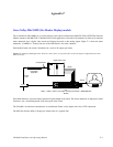
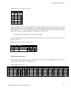
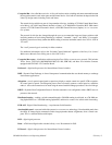
Input Set. This placeholder set, type Serial, must be created with at least one Entry number and one Logical Input.
See Figure T−3.
Figure T−3. Placeholder Serial−type CP Input Set (example).
1
Input Set — MNF−IN
2
Entry
BARS
Input
0
Logical
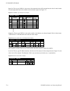
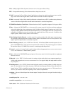
Output Set. This set, type Serial, is used to assign a router output to each OSD channel.