


Hardware Installation
2−68 CM 4000 Installation and Operating Manual
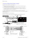
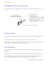
MI 3040 HARDWARE OVERVIEW
Relay Outputs
The MI 3040 provides 40 electrically isolated output connections for operating tally lights, using solid−state switches which
are suitable for low−voltage (<100 V), low−current (<300 milliamps) applications.
Note 1: The Jupiter Tally system can only operate tally lights for sources that are connected directly to the Jupiter−
controlled router as inputs. If a source is instead connected to a production switcher, or to a non−Saturn, non−MCS
2000 master control switcher, then the tally light for that source must be operated by that switcher’s tally relay
system—not by the MI 3040.
Note 2: When the master control switcher feeds the transmitter indirectly (by re−entry through the routing
switcher), a relay number must be entered on system configuration tables (as described in detail later) for a tally
light assigned to the master control switcher. Relay numbers must also be entered on system tables for tally lights
mounted next to production switchers. However, physical installation of these lights is optional. Whether these
lights are installed or not, the sources upstream of the switcher(s) will still be tallied.
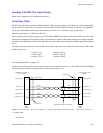
Status Inputs (Opto−isolators)
40 opto−isolated inputs are provided on the MI 3040 to receive tally data from production switchers and/or non−Saturn, non−
MCS master control switchers, allowing the Jupiter system to determine what source has been selected by such switchers.
This information is used along with Jupiter−controlled router status data to illuminate the appropriate tally light(s).
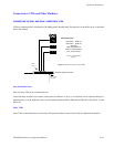
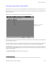
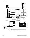
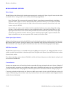
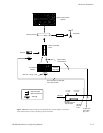
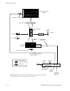
MPK Bus Connections
The MI 3040 connects directly to a CM 4000 serial port using MPK protocol (Figure 2−81). Multiple MI 3040s can be in-
stalled as needed. Since information is shared among all units, tally lights can be operated by one MI 3040 based on switcher
data received at another.
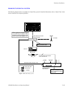
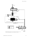
For a Saturn stand−alone system, where no CM 4000 is available, the Saturn video processor (either digital or analog) is used
as the source of the MPK bus.
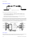
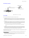
Current Sources
In many cases current sources will need to be found to operate the tally lamps and energize the opto−isolators. Although +5
V and ground utility connections are available on the back panel of the MI 3040, this supply may not be sufficient for the
particular installation. Before attempting these connections, please refer to the hardware overview starting on page 2−77.
Connecting production switchers and/or non−Saturn, non−MCS master control switchers to the MI 3040 opto−isolators will
require an understanding of the switcher’s tally relay hardware. Please refer to the installation manual supplied with the
switcher for more information.