


Configurator
CP Output Set
5−78 CM 4000 Installation and Operating Manual
CP Output Set
1
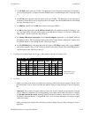
Output Set — MC−OUT
Category
STU
Entry
1
Mnemnonic
QC
Output
QC
Level Set Button
2
3
VTR 1 VT01 VT01
VTR 2 VT02 VT02
1
Output Set — NEWS−OUT
EJ 1 NEW1 NEW1
2
3
EJ 2 NEW2 NEW2
EJ 3 NEW3 NEW3
4 VTR 3 VT03 VT03
5
6
VTR 4 VT04 VT04
VTR 5 VT05 VT05
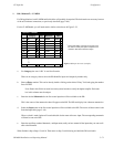
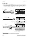
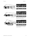
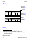
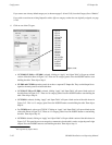
Figure 5−64. CP Output Sets (example showing new Auto Mnemonic column).
Auto
Mnem
Category Entry Mnemnonic Level Set Button
Auto
Mnem
Logical
Output
Logical
Password 5−22
Network Description 5−27
Serial Protocol 5−30
Switcher Description 5−35
Switcher Input 5−48
Switcher Output 5−55
Control Panel Sets
Level set 5−58
Input set 5−62
Output set
Override set 5−96
Sequence set 5−99
Category set 5−101
MPK Devices 5−107
Machines 5−135
Machine Control 5−139
Delegation Groups 5−149
Status Display Header 5−150
VGA Status Display 5−151
Tally 5−152
Path Finding 5−174
Exclusion 5−188
Y Line 5−189
Time Standard G−11
Video Reference G−14
CM VGA Options H−1
OVERVIEW
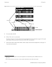
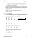
Category Entry Mnemnonic Output
Links category/entry numbers and mnemonics to switcher outputs.
The Output Sets are assigned to specific control panels on the MPK devices table (page 5−107).
Important: Do not give an Output Set the same name as an output. Use of an extension such as “OUT” is recom-
mended to help avoid potential conflicts.
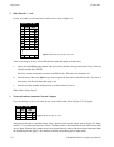
Since each control panel can be assigned a different CP Output Set if desired, these sets are usually used to control access
to outputs on a panel−by−panel basis: