


Configurator
Path Finding
5−185CM 4000 Installation and Operating Manual
Non−Sequential Path Finding
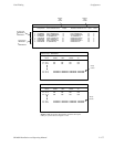
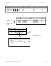
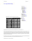
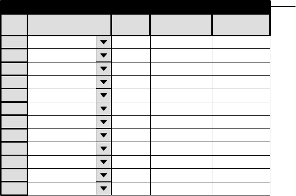
Figure 5−158. Non−Sequential Path Finding data table (example).
1
Non−Sequential Path Finding
Path Finding
GROUP1
Line
3
Physical
83
Physical
87
2 GROUP1 4 84 88
3 GROUP2 3 83 87
4 GROUP2 4 84 88
5 GROUP3 3 83 87
6 GROUP3 4 84 88
7 GROUP4 3 83 87
8 GROUP4 4 84 88
9 GROUP5 2 82 20
10 GROUP6 2 82 20
11 GROUP7 2 82 20
12 GROUP8 2 82 20
Number Output Input
Group Name
Password 5−22
Network Description 5−27
Serial Protocol 5−30
Switcher Description 5−35
Switcher Input 5−48
Switcher Output 5−55
Control Panel Sets
Level set 5−58
Input set 5−62
Output set 5−78
Override set 5−96
Sequence set 5−99
Category set 5−101
MPK Devices 5−107
Machines 5−135
Machine Control 5−139
Delegation Groups 5−149
Status Display Header 5−150
VGA Status Display 5−151
Tally 5−152
Path Finding
Exclusion 5−188
Y Line 5−189
Time Standard G−11
Video Reference G−14
CM VGA Options H−1
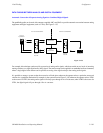
The path finding software option has already been described in detail, starting on page 5−174.
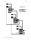
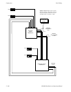
The Non−Sequential Path Finding table must be used if the tie lines joining the switchers are not wired sequentially, i.e., not
wired as blocks. Basically, the table is designed to enter “exceptions” to the Sequential table. For example, a new tie line that
falls outside the original sequence can be defined on the Non−sequential table; the only change then needed on the Sequential
table would be to increment the “Count” number for the group by 1. (Alternatively, you may prefer to use the Non−sequential
table to define all tie lines individually.)
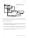
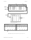
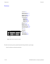
An example system is shown on page 5−186, with corresponding tables shown on page 5−187. Notice that the Path Finding Data
table, and the Switcher Input tables, must still be used as described in the previous section.