


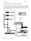
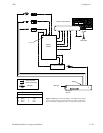

Configurator
Status Display
5−151CM 4000 Installation and Operating Manual
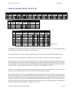
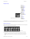
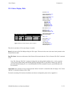
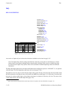
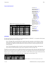
VGA Status Display Table
1
VGA Status Display Table
Board
CM1
Page File Name
VGA01
Video Mode
VC8
2
Figure 5−131. VGA Status Display table (example).
Password 5−22
Network Description 5−27
Serial Protocol 5−30
Switcher Description 5−35
Switcher Input 5−48
Switcher Output 5−55
Control Panel Sets
Level set 5−58
Input set 5−62
Output set 5−78
Override set 5−96
Sequence set 5−99
Category set 5−101
MPK Devices 5−107
Machines 5−135
Machine Control 5−139
Delegation Groups 5−149
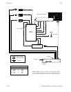
Status Display Header 5−150
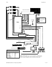
VGA Status Display
Tally 5−152
Path Finding 5−174
Exclusion 5−188
Y Line 5−189
Time Standard G−11
Video Reference G−14
CM VGA Options H−1
This table is used when a VGA status display is installed.
Board is the name of the CM 4000 providing the VGA output. This must be the same as the name already entered on the
Network Devices table.
Page File Name is the source of the name of the file that will be created when the “Tools > Generate VGA Files” command
is run.
Note: The “Generate VGA Files” command is designed for use during initial installation only—it always uses the
original factory default settings when building the Page Description file. If you decide to modify your VGA dis-
play with custom formatting, do not re−run the Generate VGA Files command. If you do, your modifications will
be overwritten.
Video Mode allows selection of color or black and white. When “Color 80” is selected the table will display “VC8;” when
“B/W 80” is selected the display will be “VB8.”
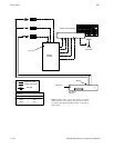
For details concerning VGA hardware installation and software configuration, please refer to Appendix A.