


Configurator
5−11CM 4000 Installation and Operating Manual
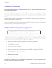
MAKING THE DESIRED MODIFICATIONS TO THE SET
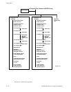
Editing procedures for specific modifications are described later in this manual, starting with the Network Description table
on page 5−27. From the Network Description table, you should move on to the Serial Protocol table, then the Switcher De-
scription table, and so on through the remaining Jupiter tables. See page 5−12.
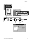
Note: As previously explained, you cannot enter data on “secondary” tables first. For example, you must enter a
new CM 4000 on the Network Description table. In general, data should be entered in the same order as the tables
appear in the pull−down menu. For more information, see “Automatic Table Entry” on page 5−3.
Not all tables will apply to every system. For example, some are for machine control, others are for backward compatibility
with Philips/BTS Party Line equipment, etc. Please refer to the description of each table for more information.
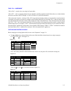
USING THE “NUMERIC” SETS FOR QUICK SWITCHER CHECKOUT
The factory−supplied numeric configuration sets can be used to set up and operate the routing switcher in the
minimum possible time. The “NUMERIC” set provides for a switcher with up to 256 inputs, 256 outputs, and
four levels; the “NUM−64” set provides for 64 inputs and outputs; and the “NUM−128” set provides for 128
inputs/outputs.
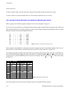
The numeric sets are complete and ready to download, except for entry of at least one CM 4000 Control Chassis
address, entry of the actual switcher Physical Levels and Driver types, and one switcher control panel address.
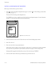
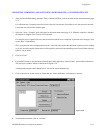
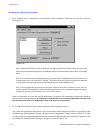
Use the “File > Open” menu to select one of the Numeric sets and make a copy (as described on page 5−10.)
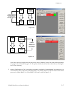
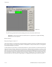
Select “Jupiter > Network Description” table and change the CM 4000 address(es) to match those in your sys-
tem (see page 5−27). The actual switcher Physical Levels and Driver types are entered on the Switcher Descrip-
tion table (page 5−35). The control panel address must be entered on the MPK Devices Description table (page
5−107).
The set can then be compiled and activated as described on page 5−13.
Inputs and outputs are selected numerically, using the TEST key on a CP 3000 control panel to enter a leading
zero for selections zero through 99. The VTR key is used to enter a “1,” and so on. For complete CP 3000 operat-
ing instructions, see page 6−7.
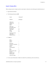
Quick Start Tip