


CM 4000 Installation and Operating Manual R−1
Appendix R
Status and Error Codes
CB 3000 CROSSPOINT BUFFER AND INTERFACE
OUT 2
OUT 3
OUT 4
OUT 5
OUT 6
OUT 7
OUT 0
OUT 1
OUT 2
OUT 3
OUT 4
OUT 5
OUT 6
OUT 7
OUT 0
OUT 1
INPUT
OUTPUT
FAN
MEM.CLR
SELECT B
SELECT A
DS1
S1
S2
S3
DS2
DS3
DS4
DS5
DS6
DS7
DS8
DS9
DS10
DS11
DS12
DS13
DS14
DS15
DS16
DS17
DS18
DS19
OUTPUT BUS FAULT 0−7
RED LEDS RED LEDS GREEN LEDS
OUTPUT DRIVRS A OR B ACTIVE
ON = A OFF = B
FAILURE ALARMS
3 SWITCHES NOT
ACCESSIBLE THROUGH
FRONT PANEL
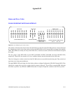
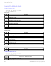
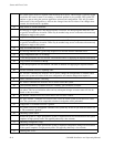
Figure R−1. CB−3000 front panel status window.
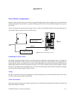
The window on the front of the chassis allows the fault indicators on the front of the CB−3000 card to be viewed. (See Figure
R−1) Beginning at the left side of the window, the first eight RED LEDs are DS1 through DS8, the Output Fault Memory
LEDs. These LEDs are normally off. If any of the LEDs are on, a fault has occurred at some time on the indicated crosspoint
bus output.
The next group of three RED LEDs are the INPUT_FAILURE, OUTPUT_FAILURE, and FAN_FAILURE LEDs,
respectively. These LEDs are normally off. An on condition indicates the fault described by the LED name.
Three local changeover switches on the front of the CB−3000 card are not accessible from the front panel. They are the local
equivalent to the front panel pushbuttons.
The eight GREEN LEDs at the right side of the display window are Output Configuration LEDs DS12 through DS19. They
indicate the A output drivers are active on their respective outputs, 0 through 7. These LEDs are normally ON, indicating
the default A position. Any LED that is OFF indicates that its respective output has switched to the B driver position.