


Configurator
Path Finding
5−175CM 4000 Installation and Operating Manual
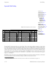
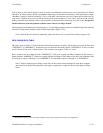
If all tie lines are busy and an attempt is made to switch to an additional upstream source, the control panel will indicate
“Blocked.” In order to release a tie line, a downstream output using a tie line must be switched to a local input. In this example,
“MainRout” output 55 could be switched to VT16, or some other source known to be a local input (such as black burst). In
some cases, it might be necessary to switch more than one downstream output to a local source, since the tie line could be
feeding more than one destination. Since it may be difficult to determine the overall usage of a given tie line, the operator
should switch away from the upstream switcher source when it is no longer needed.
†
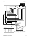
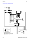
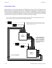
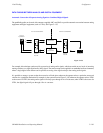
Following hardware installation (discussed on page 2−33), path finding requires entries to the Path Finding Data table and
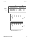
selection of Group Names numbers on the Switcher Input tables (Figure 5−151).
Note 1: If the tie lines are wired non−sequentially, please refer also to Non−sequential Path Finding on page 5−185.
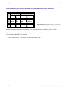
PATH FINDING DATA TABLE
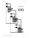
This table, shown in Figure 5−151, describes the tie lines between the two switchers. The first four rows show the lines from
“NEWSROUT” to “MAINROUT,” and the next four rows show the lines leading back to “NEWSROUT.” In this case, there
are tie lines for all four levels of both switchers. The columns are arranged in “from—to” order.
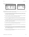
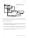
Row 1 describes lines from Input Switcher “NEWSROUT,” Video level, starting with Physical Output 10. The lines go to
Output Switcher “MAINROUT,” Video level, starting with Physical Input 43. Since there are five lines, and connections must
be consecutive, outputs 10 through 14 of “NEWSROUT” are connected to inputs 43 through 47 of “MAINROUT.”
Note 2: When a switcher input or output is used with a tie line (such as Physical Output 10 in the above example)
and entered in the Path Finding Data table, that input or output must not appear in the Switcher Input or Output
tables.
†
With Jupiter version 4.0, the VGA Status Display can be made to display tie line status. See Appendix A.