


Configurator
Switcher Input Table
5−52 CM 4000 Installation and Operating Manual
DATA SWITCHING APPLICATIONS
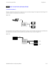
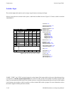
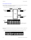
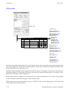
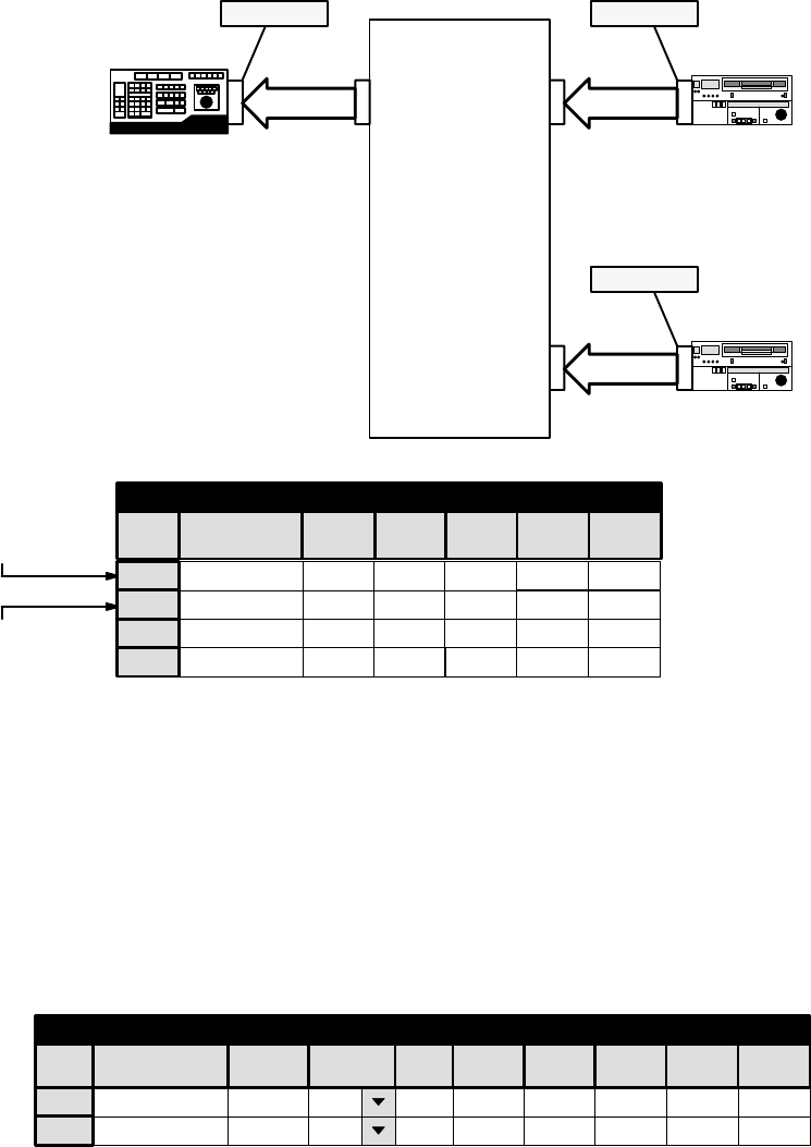
In Venus DM 400B data switching applications, the switcher input table is used to assign a logical name to each physical port
connected to a “tributary” device. See Figures 5−38 and 5−39.
Note: Configuration of DM 400/400A Data Matrix boards is described in Appendix L.
Port 00
DM 400B Data
Matrix
Controller
Editor selected
as switcher
OUTPUT
Port 01
Tributary
Tributary
Port 02
VTR 1 selected
as switcher
INPUT
VTR 2 selected
as switcher
INPUT
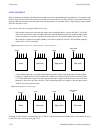
Figure 5−38. Example of DM 400B system.
For a discussion
of the “Safe” input,
see page 5−46.
See Note 1.
1
VT01
2
VT02
3
SAFE
001
002 002
Switcher Input − MAINROUT
002
001 001 001 001
064
002 002
EDIT1 000 000 000 000 000
4
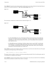
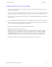
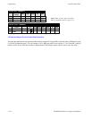
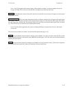
Figure 5−39. Switcher Input table
for system shown in Figure 5−38.
Name
RIGHTVIDEO LEFT TC DATA
Logical Input
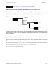
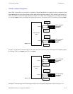
Similarly, the switcher output table is used to assign a logical name to each physical port connected to a “controller” device.
See Figure 5−40.
Note 1: All port numbers that reside in the Switcher Output table must also have an entry in the Switcher Input
table (This is done to avoid possible Status display problems and is checked by the PC compiler).
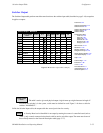
Figure 5−40. Switcher Output table for system shown in Figure 5−38.
1
Switcher Output − MAINROUT
EDIT1 −
2 −
Name
Security S−T
Pass
word
RIGHTLEFT TC
000 000 000
DATA
000
VIDEO
000
Logical Output