


Hardware Installation
2−14 CM 4000 Installation and Operating Manual
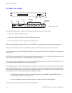
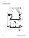
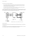
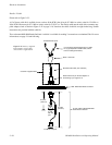
Up to 20 chassis can be connected in one MIDI loop.
Note 1: Some Triton switchers have front−panel controls. to be shown on Jupiter control panels. These controls
will operate normally when the router is connected to a Jupiter system but Jupiter 6.0 and after software is required
in order for Triton status to be indicated on Jupiter panels.
Note 2: All RS−232/422 connections should be complete and all MIDI bus loop connections should be made and
terminated at the originating device before applying power to the Triton router.
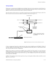
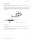
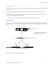
In order for a Triton analog video router to switch on Vertical Interval as set in the Switcher Description Table, rear−panel
DIP 7 must be DOWN and a sync reference signal must be connected to Input No. 1. The reference signal must be composite
video, 1 Vpp, 300 mV sync, 75 ohms. For more information, refer to the Triton manual.
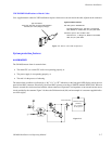
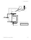
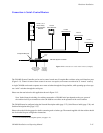
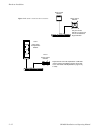
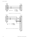
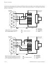
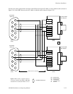
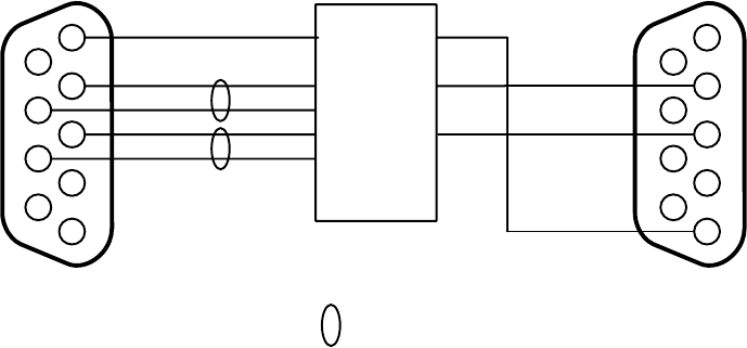
Figure 2−14. Cables for connecting CM 4000 to Triton RS−232 port.
1
6
R−
2
7
3
T−
8
4
9
5
R−
T+
to CM
serial port
G Ground
R− Receive minus
R+ Receive plus
T+ Transmit plus
T− Transmit minus
DB9P
(male)
= twisted pair
T+
R+
R+
T−
GG
Rx
Tx
G
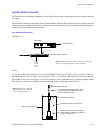
RS−422/232
converter
DB9P
(male)
Rx
Tx
1
6
2
7
3
8
4
9
5
G
to Triton
RS−232 Port
G Ground
Rx Receive
Tx Transmit
Software Configuration
The CM connected to the Triton router must be configured using the Network Description table (page 5−27) and Serial Proto-
col table (page 5−30).
Triton configuration is similar to that for other routers, beginning with the Switcher Description table (page 5−35). From that
point, switcher inputs, outputs, a CP Level Set, and CP input/Output Sets must be defined.