


Control Panel Operation
MC 3000
6−131CM 4000 Installation and Operating Manual
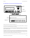
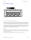
MC 3000 Machine Control Panel and CP 3010 Expansion Panel
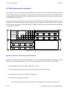
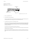
Figure 6−163. MC 3000
machine control panel
Variable speed
knob
Direction
indicator
00:54:49:11 T1
VT01 STOP MAN
TAKE
−−−−−−
SEL
TAKE
−−−−−−
SEL
TAKE
−−−−−−
SEL
TAKE
−−−−−−
SEL
TAKE
−−−−−−
SEL
TAKE
−−−−−−
SEL
TAKE
−−−−−−
SEL
TAKE
−−−−−−
SEL
>>>>>>>>
∧
∨
Status
STOP STOP STOP
VT01 VC01 VC02
Device
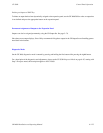
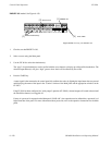
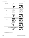
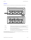
Figure 6−164. CP 3010
expansion panel
SET
MARK
VARPLAYSTOPRDY SRCH
MARK
REC
OUT
REC
IN
REC
MODE
<< >>
>>
Installation of these panels has already been described (page 2−37).
The MC 3000 machine control panel includes a series of push buttons for motion control (PLAY, STOP, etc.). A variable speed
knob, with a color−coded direction/speed indicator, is also included.
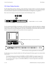
The machine to be operated can be selected using the adjacent CP 3010 expansion panel (Figure 6−164), which can display
the names of eight linked machines over a row of selection buttons. Additional pages of eight machines can be called up for
display in the window as required.
The method by which machines are linked (assigned) to the CP 3010 is described in detail elsewhere in this manual (see As-
signing Machines to Control Panels on page 5−141). Essentially, each TAKE/SELECT button is “associated” with a particu-
lar output of the routing switcher and switching a VTR to that output will cause the VTR to appear over the button. This “fol-
low−the−switcher” concept should be understood before operating either of these panels.
The CP 3010 can also be used as a limited−function machine control panel, providing Start and Stop commands for VTRs.