


Configurator
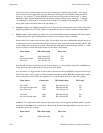
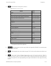
Switcher Description Table
5−36 CM 4000 Installation and Operating Manual
ENTERING SWITCHER LEVELS DESCRIPTIONS
1. On the top of the Jupiter Configurator window (page 5−2), check to see whether the configuration set you want to
change is selected for editing.
In most cases, you will want to modify the set that is currently active; if so, you may want to copy the active set and
select the copy for editing. For more information, please see Copying a Configuration Set for Editing on page 5−10.
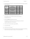
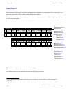
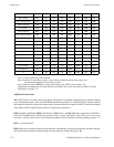
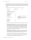
2. Click on “Jupiter > Switcher Description.” This will open a table similar to that shown on page 5−28.
3.
Switcher Level
Enter a switcher and level name.
Guidelines for using the editor are found on page 5−3.
Important: Row numbers on Jupiter tables are used as the “logical” numbers for levels. Changing the row number
of a level (by inserting/deleting a new level in the middle of the table, for example) will disrupt control of the
system, requiring controller boards to be memory−cleared and reset (see “Clearing Battery−Protected Memory”
in Appendix B). One way to avoid this interruption is to add new levels at the end of tables. Adding new levels
in the middle of the table will also clear all entries in the Switcher Input and Output tables.
Normally one switcher is named, using up to eight characters.
The level name (also called “logical level name”) can also be up to eight characters. All of the following information
entered on this menu will apply to this level. Conventional names are “VIDEO,” “LEFT,” “RED,” “GREEN,”etc.
For a Venus “ES 401”
§
digital audio switcher with two−level stereo mode hardware settings, there must be an entry for
the Left level and another for the Right level; this will allow special stereo mode switching such as Mix and Reverse.
If the ES 401 switcher’s hardware is set for one−level stereo mode, or for one−level mono mode, or if a Venus “ES 400”
digital audio switcher is being configured, only one entry is needed. For information about setting the Venus hardware,
refer to the Venus Installation manual.
If there is more than one Grass Valley Crosspoint Bus router
‡
type in the system (such as a Venus plus a Trinix), there
are two possible approaches to configuration. The additional switcher can be entered as a named level (or levels) within
the main router; however, this will require a unique hardware setting on each level to avoid conflicts (see diagram on
page 2−31). Another solution would be to drive the Venus with one CM 4000 and the Trinix with another; this would
allow level settings to remain independent (see diagram on page 2−32).
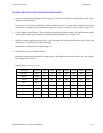
4.
VI
Select vertical interval switching Yes or No for this level. Normally checked for the video level and unchecked
for all others.
If the CM 4000 is supplied with house reference sync, checking VI will cause switches on this level to start in the house
vertical interval. In other words, the level selected on this menu will start switching first; other levels will follow as soon
as possible. Priority is normally given to video since audio switches outside of vertical interval are not as noticeable.
§
In this manual, “ES 401 switcher” refers to the AES11 synchronous/asynchronous version of the digital audio switcher
matrix board and its associated components; “ES 400 switcher” refers to the original asynchronous (non−reclocking) ver-
sion of the digital audio switcher matrix board and associated components.
‡
“Crosspoint Bus routers” are listed on page 1−11.