


Control Panel Operation
CP 3020
6−26 CM 4000 Installation and Operating Manual
CP 3020 Push Button Control Panel operation
Installation of this panel is shown on page 2−37. See also page 2−43.
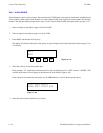
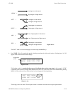
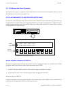
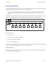
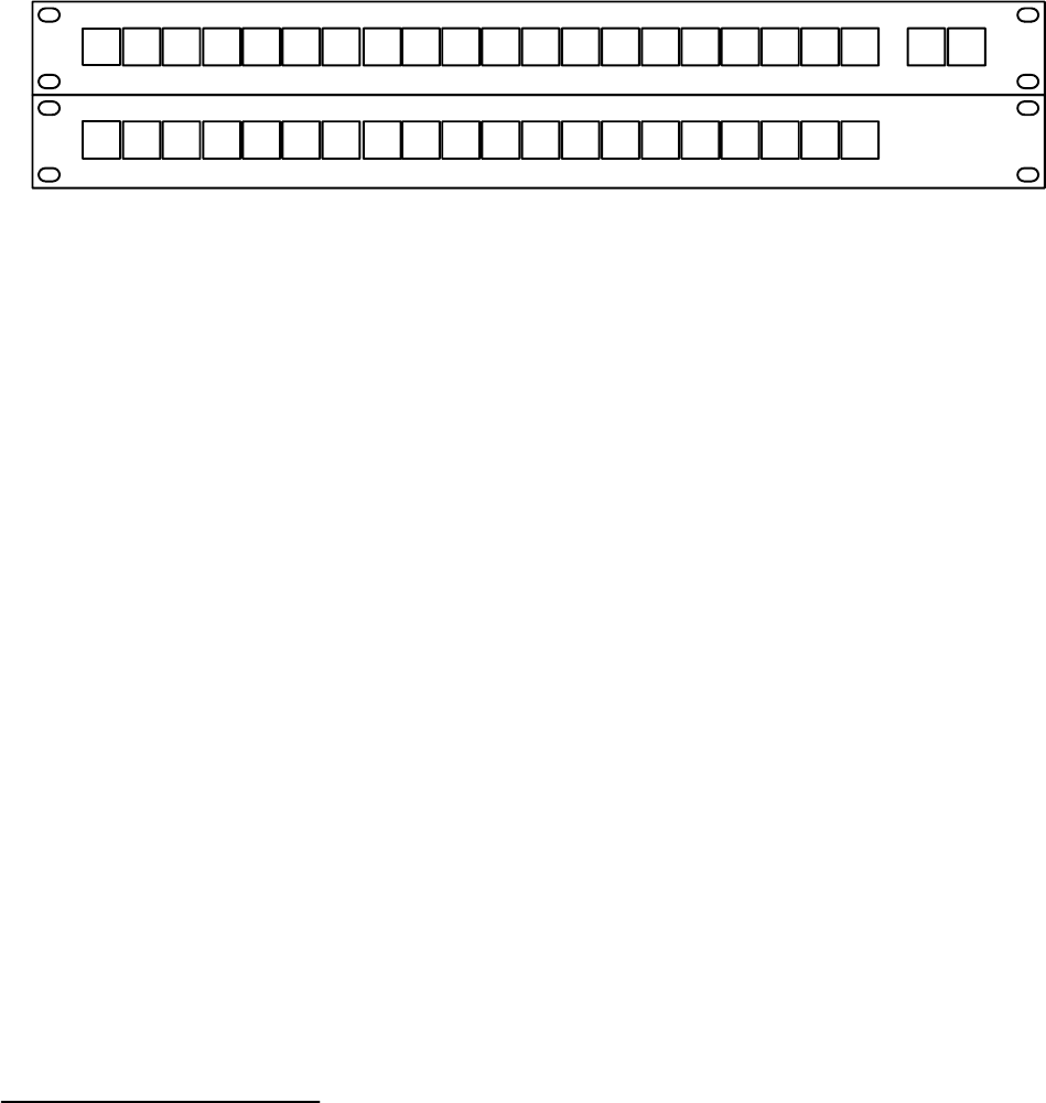
The CP 3020 is a single bus control panel that can select one of 20 inputs using the button−per−input technique. The number
of inputs can be increased by means of the CP 3021 Expansion Panel.
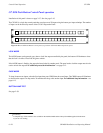
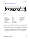
Figure 6−28. CP 3020 Push Button Control panel (top) with CP 3021 Push Button Expansion panel.
82 41 42 DM
C1 C2 C3 C4 T1 T2 R1 R2 NTV1 V2 V3 V4
V5
SA SB E1 E2 E3
LOCK CHOP
LO1 LO2 LO3 LO4 81M1 M2 M3 M4 M5 LR LS P1 P2 P3
V6
RR
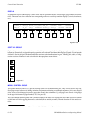
LOCK MODE
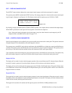
The LOCK button can be pressed at any time to lock* the output controlled by the panel; the button will illuminate to show
that the lock is in effect. Press LOCK again to unlock.
If the LOCK button is flashing, the output has been locked by another panel. The panel used to lock the output must also be
used to unlock the output. For additional protect/lock information − see page 6−12.
CHOP MODE
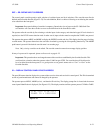
To chop* between two inputs, select the first input, then press CHOP, then the second input. The CHOP button will illuminate
to show that the output is in chop mode. To terminate the chop, select another input. For additional chop information − see
page 6−13.
BUTTON/LAMP TEST
See page 2−59.
*see Glossary
§
A complete copy of this manual is also available on the Technical Publications Library CD−ROM supplied with the manu-
al you are now reading.