


Configurator
Switcher Output Table
5−55CM 4000 Installation and Operating Manual
Switcher Output
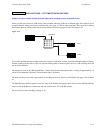
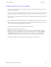
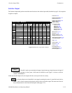
The Switcher Output table performs much the same function as the switcher input table (described on page 5−48) except that
it applies to outputs.
1
Switcher Output − MAINROUT
Name
MAT MON
Security S−T
−
VIDEO
000
2 MC QC − 001
3 PATCH 1 − 002
4 PATCH 2 − 003
Pass
5 SHOP − 004
6 VC 2P 1 − 005
7 VC 2P 2 − 006
8 VC 2P 3 − 007
word
LEFT
000
001
002
003
004
005
006
007
RIGHT
000
001
002
003
004
005
006
007
TC
000
001
002
003
004
005
006
007
9 VC 2P 4 − 008
6 VC 2S − 009
7 VT 01 − 010
8 VT 02 − 011
008
009
010
011
008
009
010
011
008
009
010
011
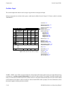
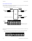
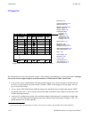
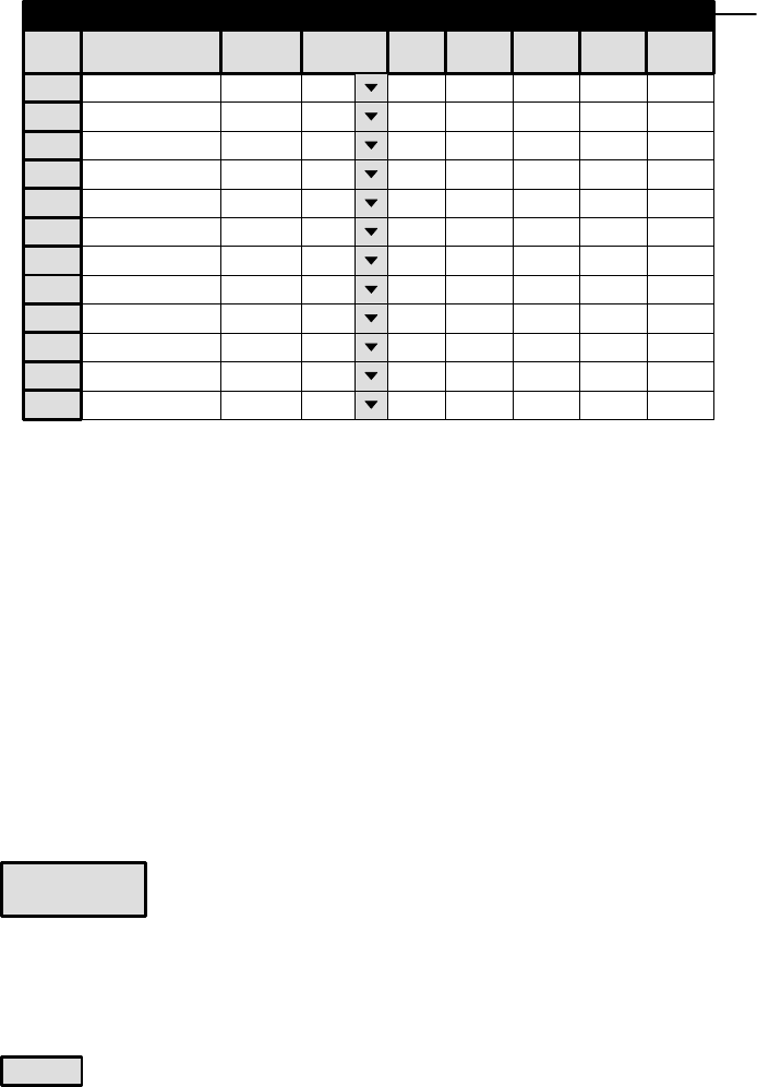
Figure 5−44. Switcher output table (example).
Logical Output
Password 5−22
Network Description 5−27
Serial Protocol 5−30
Switcher Description 5−35
Switcher Input 5−48
Switcher Output
Control Panel Sets
Level set 5−58
Input set 5−62
Output set 5−78
Override set 5−96
Sequence set 5−99
Category set 5−101
MPK Devices 5−107
Machines 5−135
Machine Control 5−139
Delegation Groups 5−149
Status Display Header 5−150
VGA Status Display 5−151
Tally 5−152
Path Finding 5−174
Exclusion 5−188
Y Line 5−189
Time Standard G−11
Video Reference G−14
CM VGA Options H−1
Logical Output
Name
The table is used to give each physical output a logical name up to eight characters in length. If
more than one switcher is in the system, a table must be defined for each. Figure 5−44 shows a table for
switcher “MAINROUT.”
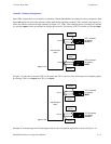
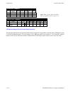
Unlike the Switcher Inputs table, the outputs table has several provisions for security:
Security
A Security Board can be identified for an output by entering the name of a controller board (such as
“CM1”); only controls connected to that board could be used to switch the output. The name must be one of
those already entered on the Network Description table (page 5−27).